| Product(s): |
SewerGEMS, SewerCAD, StormCAD, CivilStorm |
| Version(s): |
CONNECT Edition, V8i |
| Area: |
Layout and Data Input |
Problem
I would like to edit start and stop invert elevations of conduits and add/subtract/multiply/divide by a value "x" when "Set Invert to Start/Stop?" is "True"
I would like to have a fixed difference between my start invert and stop invert elevations.
Solution
Option 1
1. Open your Conduit FlexTable
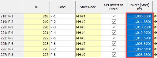
2. Global Edit the "Set Invert to Start?" column to toggle them all to True.
3. Select the cells in the "Invert (Start)" column, and Ctrl+C to copy the values to the clipboard*.
4. Undo (Ctrl +Z) the global edit (to restore the "Set Invert to Start?" column values).
5. Place the cursor on the first cell in the "Invert (start)" column and Ctrl+V to paste the values from the clipboard.
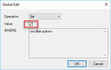
6. Global Edit the "Invert (Start)" column. Here you can perform the required function (add/subtract/divide/multiply) by choosing the same in the "Operation" field. After this enter the desired value.
Refer Global Editing Element Information for more details
7. Do the same for the Invert (Stop).
Note: When working on Invert (Start/Stop) you can use the operators add/subtract/multiply/divide to incorporate the difference between them. When working on Invert (Start) "add/multiply" to increase the value than Invert (Stop). When working on Invert (Stop), "subtract/divide" to decrease the value then Invert (Start). You can choose either of the approaches to get the desired constant difference.
*In Step 3, do not click the column header when selecting the cells to copy. That is easier, but it will include the column header text on the clipboard, so would not paste properly in Step 5.
Option 2
The best way is to do this with a 'design' run, where the software will do an constraint based run and set the inverts.
See QuickStart Lessons (for SewerCAD) > Lesson 2 > Automatic Design in the Help for more details.
There is one key step that you should also perform, and that is to set the Matchline Offset field appropriately. Here are the steps.
1. For V8i versions; Go to Components > Default Design Constraints. For CONNECT Edition versions; Go to Analysis > Analysis Tools > Design Constraints.
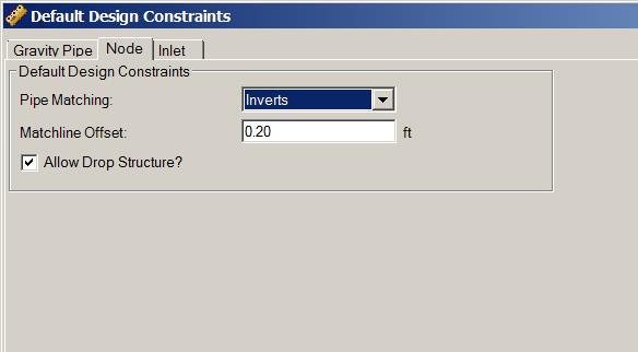
2. Click on the Node tab
3. Make sure 'Pipe Matching' is set correctly (you want to match 'Inverts')
Set the Matchline Offset field to "0.2 ft" (as an example)
Now when you perform the design run, your inverts will have a 0.2 ft offset.
See Also
Global Editing Element Information
Troubleshooting Constraint Based Design Results