| Applies To | |||
| Product(s): | AutoPLANT Isogen | ||
| Version(s): | XM, V8i | ||
| Environment: | N/A | ||
| Area: | N/A | ||
| Subarea: | N/A | ||
| Original Author: | Derek Cornell, Bentley Technical Support Group | ||
Overview
Isogen has the ability to allow for changes to or replacement of the symbols used for most components in the iso drawings. This is a technote that shows the process of modifying a symbol via the Symbol Editor using the example of a level gauge.
Solution
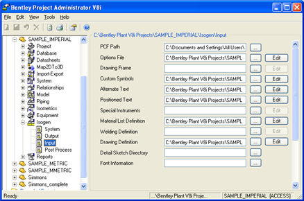
- Start the Project Administrator.
- Browse to the Current Project > Isogen > Input Options.
- Select the Edit button next to the Custom Symbols and the Symbol Editor will open with a newly created custom symbols file (*.ASC).
- In the menu, go to View > Standard Library.
- In the pull down menu on the top left of the screen, go to "Redefining Instruments".
- In the pull down menu on the top center of the screen, go to "Old SKEY: II - Instrument"
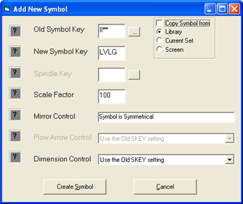
- Go to the menu: Symbol > New - Create a New Symbol in the Current Set.
- In the top right section of the dialog, uncheck the option "Copy Symbol From".
- Enter a new SKEY. As an example, this SKEY will be called LVLG.
- Select the button Create Symbol.
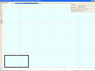
- Now draw the new symbol.
Note: The first point selected will also insert the "Start Point" node (green). This should be on the left center of the symbol . The component must have an End point (red). After creating all the lines in the symbol, then select the END icon from the toolbar and insert the END node. Three tap port nodes should be inserted for the instrument gauge (yellow) (located in the top center, center and bottom center of the component). - After creating all the necessary parts of the symbol, select DONE from the toolbar.
- Go to Files > Save As...
- Save the file to its default location with the default name (FINAL.ASC).
- Exit the Symbols Editor.
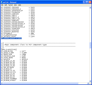
- Now open the following file in Notepad ..\PLANT V8i\MODULES\INSTRMNT\PCF.INI.
- Search for the section MAP_CLASS2SKEY.
- Add a new line at the end of this section:
AT_GAUGE_HORIZ = LVLG - Save and close the file.
- Now restart AutoPLANT and open a model in this project.
- Run the model through Isogens.
See Also
External Links
Bentley Technical Support KnowledgeBase
Comments or Corrections?
Bentley's Technical Support Group requests that you please confine any comments you have on this Wiki entry to this "Comments or Corrections?" section. THANK YOU!