| Applies To | |||
| Product(s): | Microstran | ||
| Version(s): | V8i | ||
| Environment: | N/A | ||
| Area: | Design | ||
| Original Author: | Bentley Technical Support Group | ||
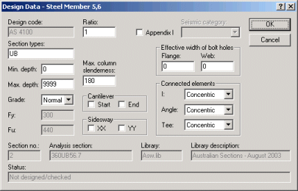
Optional steel design modules require the input of member design data. When you initialize members for design, default design data is allocated. You must specify items such as the type of section to be selected and the grade of steel. These and other items are shown in the Design Data dialog box, below, which appears when you select the Design > Design Data > Input/Edit command. Alternatively, you can right-click on a member and choose Edit Design Data.

STEEL DESIGN DATA
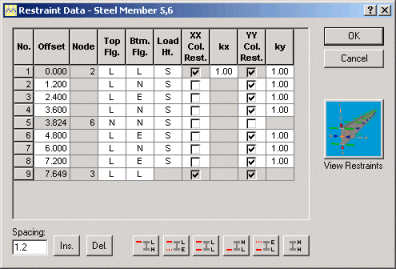
The Restraint Data dialog box is displayed immediately after the Design Data dialog box. In it, you must describe any restraints that will affect the design. There are two types of restraint for steel design - restraints against lateral torsional buckling (LTB), and column buckling restraints.
LTB restraints include members connected to one or both flanges to inhibit instability when the design member is subjected to bending. Column buckling restraints inhibit the buckling of the design member when it is subjected to compression. Some restraining members (e.g. purlins) may provide both LTB and column restraint.

STEEL DESIGN RESTRAINT DATA
When you initialize a design member, which may comprise more than one analysis member, LTB restraints are provided at each end. If there are intermediate LTB restraints, they must be specified in the Restraint Data dialog box. Clicking the Ins. button will insert a new offset before the highlighted offset while clicking the Del. button deletes the highlighted offset. New offsets are inserted with the spacing shown in the Spacing edit box.
LTB restraints are described with codes - L means effective lateral restraint, E means elastic restraint, and N means no restraint. Column buckling restraints are specified by checking the XX and YY Col. Rest. check boxes at the offset of the restraint. Wherever a box is checked, the adjacent cell contains an effective length factor. This factor is applied to the length to the next check mark.
In AS 4100 and NZS 3404, each section along the design member where there is an LTB restraint is classified as fully or partially restrained or unrestrained. These section restraints are derived automatically by Microstran for each design case, according to the flange restraints that you input in the Restraint Data dialog box and the critical flange location. Sometimes, you will need to input flange restraints for a design member that does not have flanges, e.g. a hollow section. In these cases, you should input the flange restraint codes that correspond to the desired section restraint code. For example, where you regard a section in an angle design member as being partially restrained, you could input flange codes of L and E to ensure this.
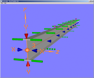
Clicking the View button in the steel design restraint dialog box shows a virtual reality window, as shown below, in which all steel design restraint data is represented symbolically.

STEEL DESIGN RESTRAINT VISUALIZATION
Simple geometric shapes are used to distinguish the different restraint types. Node and member numbers and member axes are shown so you can easily relate the design member to the structural model. You may drag the mouse pressing the left button to rotate the image or the right button to pan it.