| Applies To | |||
| Product(s): | Microstran | ||
| Version(s): | V8i | ||
| Environment: | N/A | ||
| Area: | Analysis | ||
| Original Author: | Richard Collins | ||
Plastic Analysis of Frames
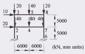
You may use Microstran's optional fuse members to perform both first-order and second-order plastic analysis of simple frames. This is illustrated with an example from page 330 of The Behaviour and Design of Steel Structures to AS 4100, 3rd Edition by Trahair & Bradford. The frame and loads are shown below in a diagram from the book.

FRAME AND LOADS
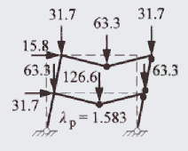
The collapse mechanism determined in the book is shown below. The calculated collapse load factor is 1.583.

PLASTIC COLLAPSE
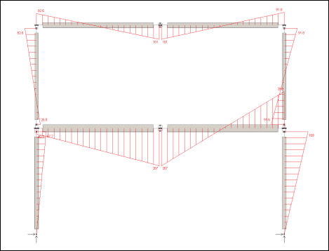
The model was analysed using non-linear analysis with second-order effects turned off, effectively a first-order analysis. With a load factor of 1.565 the bending moments and axial forces determined were within 1.5% of the published values. With a greater load factor analysis failed, indicating collapse. The model is shown below. At each location where a plastic hinge could develop, a short length of the parent section is replaced by a pair of plastic fuse members.

MICROSTRAN MODEL
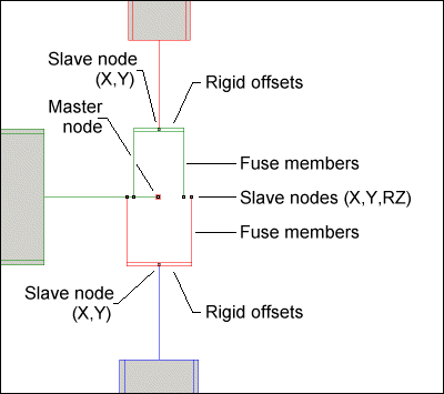
Each plastic fuse member represents the area of the parent section above or below the centroidal axis (i.e. half the area of the parent section) and is located at the centroid of this area. All other geometric section properties of the fuse member are zero. Maximum tension and compression forces are computed from the yield stress and specified for each fuse.
Each fuse member is connected at one end to the parent section by rigid offsets and the other end is connected to a node that is slaved to a master node at the intersection point. The node connecting the rigid offsets is slaved for translational DOF to the master node. For UB and UC sections, you can easily determine the centroidal offset for the fuse members by showing the properties of the corresponding tee section in the Library Manager.

PLASTIC FUSE MEMBERS