| Applies To | |||
| Product(s): | RAM Elements | ||
| Version(s): | 13.0.03.45 or later | ||
| Area: | Design |
RAM Elements - Local versus Principal Axis in Unsymmetrical Shapes
In RAM Elements, analysis and design results are referenced to a local axis system (1, 2, 3) or a principal axis system (1’, 2’, 3’).
For symmetrical sections, the local and principal axes will coincide. However, for unsymmetrical (asymmetric) sections, such as Z and L shaped sections, the principal axes will be rotated relative to the principal axes which can cause confusion for major or minor axis bending and shear checks.
The orientation of the local axes is defined as follows:
- Local axis 1 points from Node J to Node K along the member.
- Local axis 3 is perpendicular to local axis 1 in the plane of the member.
- Local axis 2 is perpendicular to the plane formed by the Local 1 and 3 axis.
The local axes can be displayed for any member by clicking on the Local Axes button in the View menu - Model Toolbar. See below:
The principal axes represent the axes about which the moment of inertia is maximum and minimum. The orientation of the principal axes is defined as follows:
- Principal axis 1' points from Node J to Node K along the member. It aligns with the Local 1 axis.
- Principal axis 3' defines the strong axis of the section. The moment of inertia about this axis is the maximum moment of inertia of the section.
- Principal axis 2' defines the weak axis of the section. The moment of inertia about this axis is the minimum moment of inertia of the section.
In version 13.05.00 and earlier, there is not a way to display the principal axes on screen. In v14.00.00 and later, the principal axes can be displayed by clicking on the Principal Axes button in the View menu - Model Toolbar. See below:
In all versions, the angle of rotation of the principal axis can be found in the section properties report under Output-Data-Section Properties.
Analysis Input and Output
Member loads can be defined with respect to the local axes or the global axes only. The tool buttons used to rotate members and create rigid end offsets use the local axes.
In version 13.05.00 and earlier, member forces displayed on screen using View – Analysis Toolbar – Member Forces are always referenced to the principal axes. Note the reference to 2’ and 3’ (and not 2 and 3) in the menu below.
This can create confusion when the principal axes are rotated 90 degrees relative to the local axes. In this case, the member loads will be displayed relative to the local axes and the member forces associated with them will be displayed relative to the principal axes. In the image below, the M22 moment is a moment about the principal 2 axis, which coincides with the local 3 axis and not the local 2 axis.
In version 14.00.00 and later, member forces are displayed with respect to the local axes by default, but can be displayed with respect to the principal axes using the option marked in the screen capture below:
Design Input and Output
In v15.00.00, double angles and WT sections are always designed with respect to the local axes. The unbraced length parameters L22 and L33 are associated with the local axes and not the principal axes.
In v14.00.00, the unbraced length parameters L22 and L33 are associated with the principal axes and not the local axes. This was not always the case. In previous versions of the program, L22 and L33 were associated with the local axes. For sections like a WT 4x15.5 that have a principal axis rotated 90 degrees relative to the principal axis, L33 should be used for the unbraced length for bending about the local 22 axis and L22 should be used for the unbraced length for bending about the local 33 axis. For symmetric sections, like a W18x50, L33 should be used for the unbraced length for bending about the local 33 axis and L22 should be used for the unbraced length for bending about the local 22 axis.
In general, steel and cold-formed sections are designed with respect to the principal axes. Prior to v13.0.3.45, cold-formed section were designed with respect to the local axis only. In AISC 360, single angles are permitted to be designed with respect to either the geometric (local) or principal axis. In RAM Elements, the steel design checks both and uses the worst-case for the design ratio. Some engineers choose to design single, equal leg angles with respect to the geometric axis only. Enhancement #277754 has been filed to do this in a future release.
The list below summarizes program changes that may explain different design results in the current version compared to an earlier version:
1. L22 and L33 are referenced to the principal axes and not the local axes. In earlier versions, these parameters were referenced to the local axes.
2. Cold-formed sections are designed with respect to the principal axes. In earlier versions, these parameters were referenced to the geometric axes.
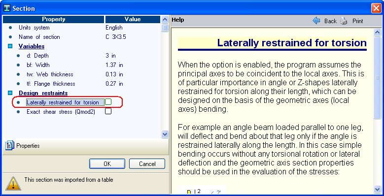
Laterally Restrained for Torsion Option
In all versions, there is a way to force the program to align the principal axis with the local axis for a particular section.
In version 13.05.00, edit the properties of the section in the Sections Database and check the box “Laterally Restrained for Torsion.” This change can only be made to user sections. For program installed sections (any section in the United States Group, Europe Group, etc), the section file will need to be copied to a user defined data folder before the laterally restrained for torsion flag can be changed.
In v14.00.00, select the member and check the box shown below for α=zero in the Members tab - Local Axes worksheet.
