Overview
With the increased use of lighter beam sizes and longer spans made possible by higher steel and material strengths and with larger, more open and more lightly load floor areas due to advances in office technology and utilization, the lighter sleeker floor systems are more susceptible to adverse vibrations than ever before. It is vital that this serviceability condition be investigated and considered during design. Three distinct methodologies for the investigation of floor vibration in steel framed floors have been incorporated into the RAM Structural System.
A traditional methodology has been implemented that is based on the Modified Reiher-Meister scale and on the work of Dr. Thomas Murray published by AISC nearly 30 years ago. However, due to the advances mentioned previously, that methodology no longer adequately predicts the actual vibrational behavior of modern floors and, in fact, AISC recommends that that methodology no longer be used. That methodology is retained in the program, for reference or comparison purposes. More information on that methodology and its implementation can be found in the RAM Steel Beam manual.
In the US the most commonly used method of analyzing floors for vibration is found in Steel Design Guide #11, “Floor Vibrations Due to Human Activity”, authored by Thomas Murray, David Allen and Eric Ungar and published jointly by AISC and CISC. The implementation of this methodology in the RAM Structural System is discussed in greater detail in this article.
In the UK the most commonly used method of analyzing floors for vibration is found in SCI Publication P354, “Design of Floors for Vibration: A New Approach”. The implementation of this methodology in the RAM Structural System is similar to that of Design Guide #11, and much of the discussion of Design Guide #11 in this article also pertains to the implementation of SCI P354; more information on the implementation can be found in the RAM Steel Beam manual. In addition, a simple method commonly used in the UK is also available in the program, but not discussed here.
Beams, Bays, and Classification
Vibration is a bay phenomenon, not an individual beam phenomenon. Thus it is important that the characteristics of the entire bay be considered, not just those of the individual beams. Design Guide #11and SCI P354 are based on this concept.
According to research, bays with irregular framing rarely experience vibration problems. Bays with beams and girders with differing lengths, orientations and stiffnesses (and hence differing vibrational properties) do not resonate and hence do not pose a problem. Even seemingly minor variations have often been found to be sufficient to prevent vibrations from achieving perceptible levels. Thus it is not necessary to analyze every beam on the floor for vibration. Design Guide #11 identifies those types of framing configurations that may be susceptible to vibration problems and then describes the procedures for analyzing them. What is often viewed as a shortcoming of the Design Guide is actually one of its strengths. It is not the case that Design Guide 11 is limited in scope in that it only describes the procedure to be used on regular orthogonal framing, but rather it is the case that the Design Guide identifies those types of framing configurations that may be susceptible to vibration problems and then describes the procedures for analyzing them. Framing schemes that vary significantly from the regular layouts illustrated in the Design Guide have rarely been found to have vibration problems.
When the Vibration command is invoked using the Vibration – AISC/CISC Design Guide #11 command or the Vibration – SCI Publication P354 command, the program first analyzes the floor framing geometry and classifies each beam based on the type of bay of which it is a part, if any. To facilitate this feature RAM Steel associates each bay with one of the following three classifications:
Perfect Bay
A “Perfect” bay is one that “perfectly” matches the regular orthogonal bays described in the Design Guide. It is one in which:
- The four columns form a perfect rectangle
- All framing within that rectangle is orthogonal
- All beams are equally spaced
Some tolerance and deviation from “perfect” is allowed for the bay to still be considered a “Perfect” bay, such as wall supports rather than columns, slightly unequal spacing, etc.
Imperfect Bay
“Imperfect” bays encompass a broad spectrum of configurations. They are bays that exhibit several characteristics of a Perfect bay, but have one or more geometric features that deviate from such. Note that in some cases the program will identify seemingly random individual beams as part of an Imperfect bay; these beams may exhibit several characteristics of a perfect bay (e.g., spacing, adjacent beam length, etc.), but it is often obvious that they are actually part of an irregular bay and hence don’t require further investigation.
Irregular Bay
All other beams are considered to be part of “Irregular” bays. An “Irregular” bay is one that does not conform to those bays described in the Design Guide. This includes, for example, beams that are not parallel to or whose lengths vary significantly from those of adjacent beams. Miscellaneous beams that are not part of a bay are also included in this classification.
In RAM Steel, the program investigates every beam to determine if it is part of a “Perfect” bay, a bay that “perfectly” matches the regular orthogonal bays described in the Design Guide; part of an “Imperfect” bay, a bay that exhibits characteristics of Perfect bays but has some geometric features that deviate from such; or are part of an Irregular bay, not part of a bay that would conform to those described in the Design Guide.
Vibration Analysis with FloorVibe
For the bays that “perfectly” match the Design Guide bays (Perfect bays), the vibration analysis is performed directly, and for those bays that exhibit some characteristic but have some deviation from the “perfect” bay (Imperfect bays), the vibration analysis is performed only after the user has “idealized” the bay by indicating how those deviations should be appropriately approximated as a “perfect” bay. For bays with beams that fall in the Irregular category no vibration analysis is performed, as that analysis would be meaningless (and probably erroneous). As explained above, no analysis is performed because according to the research no analysis is necessary; those bays do not, in real floors, exhibit vibration problems.
While it may sound enticing to have a program that investigates every beam on every floor regardless of configuration and without any intervention by the user, that does not reflect the behavior of real floors and the analytical capabilities needed to deal with them. For a unique beam in an area of irregular, non-orthogonal framing the methodology is not appropriate at all; any vibrations will dissipate into the surrounding framing before it is perceptible to a person standing near the beam under consideration. By reporting “results” for the irregular and miscellaneous beams, such a program may indicate that changes to sizes, framing or decks are necessary, when in reality they are not. Thus the engineer runs the risk of wasting time, effort and resources, to the detriment of himself and his client. By only reporting results for bays that truly need to be considered, RAM Steel is a greater assistant to the engineer in providing a good solution to a potentially ugly and costly problem.
A program called FloorVibe has been developed by Dr. Murray through his company, Structural Engineers, Inc., and is installed along with Ram Structural System CONNECT Edition. It is also available as a stand-alone application, see www.floorvibe.com. It is capable of performing a vibration analysis on floor systems consisting of composite and non-composite hot-rolled and built-up steel beams, steel joists and CMC Smartbeams. The criteria for walking excitation, rhythmic excitation and sensitive equipment have been incorporated. A link between RAM Steel and FloorVibe has been implemented. When a vibration analysis is to be performed in RAM Steel, the FloorVibe program is automatically launched with the pertinent geometric data automatically passed from one program to the other, and the analysis is performed by FloorVibe. This gives the engineer all of the power and capabilities of FloorVibe. There is likewise a program called FloorVibeUK for use with SCI P354.
When the Vibration command is invoked using the Vibration – AISC/CISC Design Guide #11 command or the Vibration – SCI Publication P354 command, the program color-codes the beams based on their classification:
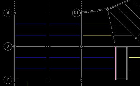
Beams in Perfect bays are displayed in blue, beams in Imperfect bays are displayed in yellow and all others (Irregular) are displayed in gray.
A beam is then selected. If the beam is part of a Perfect bay, FloorVibe (or FloorVibeUK) is launched with all of the pertinent size and geometry data exported from RAM Steel. In FloorVibe the various criteria can be set and the floor evaluated:
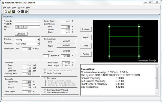
If the framing proves unsatisfactory, different beam sizes or concrete deck properties can be investigated to determine the proper modifications. The user can then make those modifications in the RAM Structural System as necessary.
If a beam is selected that is part of an Imperfect bay the program first displays a dialog showing the actual bay framing and prompting for the user to define the idealized framing that is to be used to approximate the actual framing:

When the idealized framing has been defined, FloorVibe is launched and the vibration analysis can be performed. Note that it may be necessary to ‘envelope’ the problem by investigating two or more different configurations of Idealized Framing in order to feel confident that the potential for vibration has been properly investigated. If the Actual Framing diverges too significantly from the definition of a Perfect bay it may not even be necessary to investigate vibration, as discussed previously.
If a beam is selected that has been classified as irregular, a message is given that it is not within the scope of Design Guide #11 to investigate that beam, and no analysis is performed. Remember, however, that it would be extremely rare for such beams to have a vibration problem, and hence don’t require analysis.
By partnering with Dr. Murray we have been able to draw upon his wealth of knowledge and experience. His advice and recommendations have been critical to the success of this feature. It also gives to the user all of the power of the FloorVibe and FloorVibeUK programs. The resulting combination is a very powerful, productive tool for the investigation of floor vibration.
For more information on this feature, see Chapter 11 of the RAM Steel Beam Design manual.
For vibration analysis of concrete floors, RAM Concept has powerful capabilities. See the RAM Concept v5.0 Release Notes.
See also
[[RAMSS FloorVibe FAQ]]