| |
Applies To |
|
|
| |
Product(s): |
WaterGEMS, WaterCAD |
|
| |
Version(s): |
07.XX.XX.XX |
|
| |
Original Author: |
Mike Rosh |
|
NOTE: This is a legacy article written for WaterCAD and WaterGEMS Version 7.0 from 2006. The current releases of these products do not use the same steps. See article in the "See also" section if you are using V8 XM, V8i or CONNECT Edition.
Fire flow analysis is a common tool used in WaterCAD and WaterGEMS to ensure adequate protection is provided during fire emergencies. There are two types of fire flow analysis available to the user: manual and automated. This article concerns how automated fire flows are set up and how to interpret the results.
Setup of automated fire flow analysis for WaterCAD/GEMS version 7
Steps:
1. In WaterCAD/WaterGEMS select the Analysis pull-down menu, then Alternatives
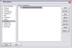
2. In the Alternatives dialog box, select the Fire Flow alternative, then click Edit
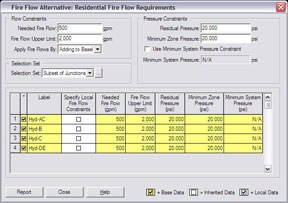
3. Specify values for the Needed Fire Flow, the Fire Flow Upper Limit, Apply Fire Flows By, Residual Pressure, Minimum Zone Pressure, and specify any Selection Set being used.
Needed Fire Flow - Flow rate required at a fire flow junction to satisfy demands.
Fire Flow Upper Limit - Maximum allowable fire flow that can occur at a withdrawal location. It will prevent the software from computing unrealistically high fire flows at locations such as primary system mains, which have large diameters and high service pressures.
Apply Fire Flows By - There are two methods for applying fire flow demands. The fire flow demand can be added to the junction's baseline demand, or it can completely replace the junction's baseline demand. The junction's baseline demand is defined by the Demand Alternative selected for use in the Scenario along with the fire flow alternative.
Residual Pressure - Minimum residual pressure to occur at the junction node. The program determines the amount of fire flow available such that the residual pressure at the junction node does not fall below this target pressure.
Minimum Zone Pressure - Minimum pressure to occur at all junction nodes within a zone. The model determines the available fire flow while assuring that the minimum zone pressures do not fall below this target pressure. Each junction has a zone associated with it, which can be located in the junction's input data. If you do not want a junction node to be analyzed as part of another junction node's fire flow analysis, move it to another zone.
Use Minimum System Pressure Constraint - Check this box if a minimum pressure is to be maintained throughout the entire pipe system.
Minimum System Pressure - You can specify a minimum pressure allowed at any junction in the entire system as a result of the fire flow withdrawal. If the pressure at a node anywhere in the system falls below this constraint while withdrawing fire flow, fire flow will not be satisfied.
4. Specify any Local Fire Flow Constraints for the system junctions
5. Click Close, then click Close in the Alternatives dialog box
6. Click GO on the main toolbar pallet on the drawing pane, place a check in the Fire Flow Analysis box, then click GO

7. View Results in Results tab. The Fire Flow Results folder will inform you whether the fire flow constraints were met or not, as well as how many nodes were computed.
Failed to Converge - This result shows how many nodes were unable to converge on a solution based upon the criteria specified in the Fire Flow Alternative.
Satisfied Constraints - Shows how many junctions satisfied the fire flow constraints specified.
Failed Constraints - Shows how many junctions failed the fire flow constraints specified
Total Nodes Computed - Shows how many fire flow nodes were computed.

8. Viewing the Fire Flow Tabular Report Results:
Close the Calculation dialog box and click the Tabular Reports button from the toolbar or click Report, then Tables.
Select Fire Flow Report

Click OK.
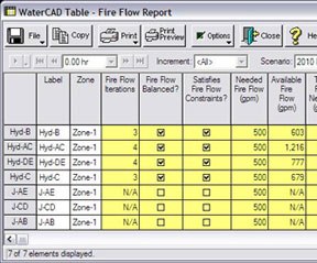
Fields in the Fire Flow Report
1. Label - Label of junction in system.
2. Zone - Corresponding pressure zone of junction.
3. Fire Flow Iterations - The number of iterations done to compute results.
4. Fire Flow Balanced? - Check box indicating whether calculations were successfully balanced during iterations.
5. Satisfied Fire Flow Constraints? - Check box indicating whether the specified fire flow was met.
6. Needed Fire Flow - Shows specified needed fire flow for calculation.
7. Available Fire Flow - Shows the available amount of water at the junction at the calculated residual pressure.
8. Total Flow Needed - Shows the amount of total flow needed at the junction during calculation. If the option to add the fire flow to the baseline demand was used, this field will show the needed fire flow plus the demand at the junction.
9. Total Flow Available - Shows the available fire flow plus the baseline demand if the option to add the baseline demand was used. If no baseline demand was added to the calculation this will show the available fire flow only.
10. Residual Pressure - Shows the specified residual pressure used during the calculation. Typically this is 20 psi.
11. Calculated Residual Pressure - Shows the pressure that was calculated for the available fire flow.
12. Minimum Zone Pressure - Shows the minimum zone pressure that was specified during setup of the analysis
13. Calculated Minimum Zone Pressure - Shows the lowest pressure calculated in the same pressure zone as the junction that had the fire flow calculated.
14. Minimum Zone Junction - Displays the name of the junction with the lowest zone pressure which corresponds to the calculated minimum zone pressure column.
15. Minimum System Pressure - Displays the minimum pressure specified across the system when this option is turned on.
16. Calculated Minimum System Pressure - Displays the minimum pressure in the system for each junction's fire flow calculation
17. Minimum System Junction - Displays the name of the junction with the lowest pressure across the entire system and corresponds to the calculated minimum system pressure column.
Keys to a successful fire flow calculation
Here are several issues that can arise during setup of a fire flow simulation:
1. Automated fire flow analysis must be set up inside the fire flow alternative. If the fire flow is set up at the junctions dialog box or inside the junction report dialog box, the fire flow will not calculate.
2. Junctions on the suction side of pumps will have a negative or near negative value, They should be moved to a different pressure zone to avoid being analyzed for the minimum zone pressure constraint.
3. Local fire flow constraints can be specified at a junction; however these will only work if the fire flow has been set up in the fire flow alternative first.
4. The Fire flow upper limit must be greater than the needed fire flow.
5. Automated fire flow analysis is steady state or one moment in time. To run an extended period simulation of a fire, additional work must be done. First run the automated fire flow analysis to determine the amount of water available at the node. Then set the junction demand to the available or needed fire flow demand and turn off the fire flow analysis. Next a pattern for the fire flow should be established and applied to the junction. Then run the extended period simulation.
6. The "Use Minimum System Pressure Constraint" option will analyze the entire system (all pressure zones) for the specified pressure setting and will stop the simulation if this pressure value is found.
See Also
OpenFlows Product Tech Notes And FAQs
Understanding Automated Fire Flow Results