Following example will explain how to download 3D symbols from 3D warehouse and use it as 3D representation for electrical symbols.
Go to utilities pull down and Select 3D warehouse>Open

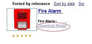
Type in desired search term. For example "fire alarm"
List of available models will come up. Select most relevant model and click on Download model.
Click yes to download to SketchUp model.
Sketchup file will open in MicroStation.
Rotate the view, so symbol has proper orientation, then go to
Edit> Copy
Go back to original file BBES Symbols.DGN and then to pull down Element >Cells
Create new cell library called BBES-Your Firm's 3D symbols.cel
Go to File open, and open this cell library
Go to Models dialog box and select New model


Select Type Design 3D and type in appropriate cell name (Fire Alarm in this example)
Make sure that option can be placed as a cell is selected.
Click Ok to create new model.
Once new model is created go to Edit >Paste
Make left click close to ACS triad.
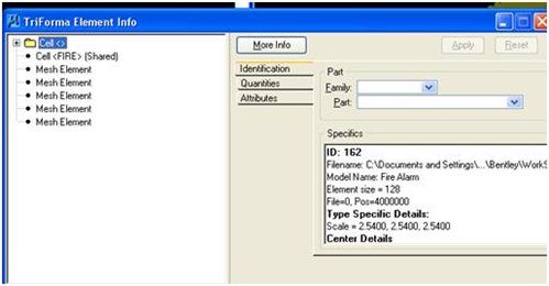
Fire alarm is now placed in cell library. Select it and go to Element Info tool.
Element info tool shows us that this symbol consists of cells and mesh elements. Our goal is to preserve all mesh elements and drop all cells to either mesh element, shapes or lines.
Identify parts of the symbol that are cells.
Clear selection set, and then select parts that are cells only (make sure that no mesh elements are selected)
Go to Drop element tool and select options Complex to segments and Shared cells to Geometry.
Select highlighted cell components with left click to drop them.


Use element Info tool to review results.
Symbols should consist only of mesh elements, shapes, and linear elements (no cells or shared cells)
In next step symbols should be rotated to proper position.
If not experienced with 3D rotation and AccuDraw functions please review all AccuDraw classes offered through Bentley Learn.
Once symbol is rotated properly, insertion point needs to be moved to 0,0,0 coordinate. Point of origin (0,0,0) will be used as insertion point for 3D symbol.
Select entire 3D symbol,
Activate MicroStation move command and make left click on insertion point for the symbol (for example center back for this alarm)
Type in M (making sure that AccuDraw is active)
Data pint key in will come up. Type 0,0,0 and hit Enter
3D symbols is now moved so insertion point is at 0,0,0.
This will insure that 3D symbol is properly inserted. Mounting height will be measured from the floor elevation to the insertion point.
Once insertion point is correct use change element attributes to change level do default . Color should be set to realistic color for this symbol instead of by level.
For example red color of. "FIRE" sign will be changed to white color
3D cell is now created and is ready to be added to Symbol Manager.
5. Adding 3D Cell to Symbol Manager:
In next step newly created 3D cell will be added to Symbol manager
Open file BBES Symbols.DGN.
Go to Element cells and attach cell library BBES-Your Firm's 3D symbols.cel
Double click on fire alarm cell to place it.
True scale should be selected and X,Y Z scales should be 1.
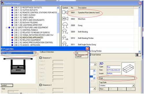
Open Symbol manager and navigate to group Other > 3D Symbolic
Scroll to the very last element and click on New
From Symbol tab go to Click and Learn
Symbol manager will disappear from screen. Select fire alarm cell with left click.
Symbol manager will come back and cell name will be displayed. Type in Symbol description
Save new 3D symbol (Save is next to Click and Learn button)
New 3D representation is now added to BBES Symbol manger and can be used as any other 3D BBES element.
Note: Make sure you are doing click and learn in TOP view.
6. Linking 2D and 3D Symbol
Following example will explain how to link 2D and 3D part of electrical symbol.
Most elements in Symbol Manager are Compound cells which means that they have 2D and 3D representation.(Exception are some Wiring Elements)
Open Symbol manager. navigate to Safety Features and equipment >Indicating Appliances and select Speaker/ Horn
Click on Edit button in 3D tab.
3D properties dialog box will open.
Select BBES Symbol and go to Select button
Symbol manager will open. Go to very last group Other and select 3D Symbolic.
Navigate to fire alarm symbol that was added in previous steps and select it.
Click OK to close 3D properties dialog box.
Save newly created symbol
2D and 3D part of the fire alarm symbol are now linked and ready for placement.
Use Insert symbol tool to place symbol.
Each Electrical Symbol is a compound cell and consists of 2D and 3D cells.
2D cell by default comes at a floor elevation (defined in building structure setup) and placement height for 3D cell is defined in each symbol placement command.
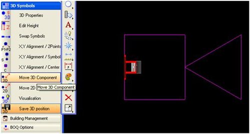
If placed 2D and 3D cell have offset, use Move 2D or 3D part of the cell to properly align them and then use Save 3D position command to save new position.
If symbols don't have properly aligned 2D and 3D representations
(as shown above) use move 3D component tool to align them.
After 2D and 3D parts is aligned use Save 3D position tool and select fire alarm symbol.
Dialog box will come up with message 3D position saved. Click OK.

Additional Info:
If you need to change point of origin (insertion point) or modify any BBES symbol it can be done in bescells.cell library located in: metadata/Symbols/ three digits folder (XXX) in your current electrical dataset. For dataset location check variable BBESDATA (Workspace>Configuration).
Open that cell library and with right click open cell for editing. Name of any existing cell in this cell library should never be changed, it will break link between Symbol Manager and this cell library and error log will be produced.