Shotcrete is often used in tunnelling and mining to seal freshly uncovered surfaces and for the support of cavities. In tunnelling, shotcrete is used at various stages throughout the process (construction and post-construction), whereas it is locally used for mining. Shotcrete is often reinforced by steel rods or steel meshes.
In PLAXIS 2D Input, reinforced shotcrete lining can be modelled using composite plate the properties of which are calculated by averaging the contribution of the shotcrete and spaced steel sets (equivalent section). In the second stage, once PLAXIS 2D analysis has been run, it is useful to plot the moments, shear forces and thrusts on support capacity diagrams in order to check whether the induced stresses in the steel sets and shotcrete lining are within permissible limits. For that, it is first necessary to redistribute the calculated thrust, moment, and shear forces at the equivalent section onto steel sets and shotcrete individual components. Once this redistribution operation has been performed, support capacity plots can be generated, and safety evaluated for both steel sets and shotcrete components independently.
With the PLAXIS 2D tunnel liner property definition and capacity evaluation tools, the aforementioned processes of calculating the equivalent plate properties in PLAXIS 2D input on one hand as well as displaying support capacity plots in PLAXIS 2D Output on the other hand can be fully automated.
For a full example, please see the article: Support capacity evaluation of a tunnel lining in PLAXIS 2D.
* Download requires Sign in to Bentley Communities.
Usage instructions for Python script
To use this Python script:
- Download the package from Downloads below
- Extract the zipped package and copy the content TunnelCompositeSectionLibrary_Input.pyw, TunnelSupportCapacityPlot_Output.pyw and shared.py files to:
[PLAXIS 2D installation directory]\pytools\shared
- In PLAXIS 2D Input, create the equivalent homogenized plate for the tunnel lining using the TunnelCompositeSectionLibrary_Input.pyw script
- In the Expert menu, go to Expert > Run Python script > Open... browse for TunnelCompositeSectionLibrary_Input.pyw
- Run the PLAXIS 2D analysis and upload corresponding results in PLAXIS 2D Output program
- In PLAXIS 2D Output, the support capacity plots for previously defined tunnel linings can be drawn using the TunnelSupportCapacityPlot_Output.pyw script
- In the Expert menu, go to Expert > Run Python script > Open... browse for TunnelSupportCapacityPlot_Output.pyw
If you do not have write access to add files to the PLAXIS 2D installation directory, you can use the following alternative approach:
- Save and extract the zipped package in a local folder
- Then, in PLAXIS 2D, go to Expert > Run Python script > Open … and browse for either TunnelCompositeSectionLibrary_Input.pyw or TunnelSupportCapacityPlot_Output.pyw depending on whether you are willing to create equivalent homogenized plate material set(s) for the tunnel lining(s) in PLAXIS 2D Input or looking to generating the support capacity plots in PLAXIS 2D Output.
Some elements of theory
The adopted methodology used to calculate the equivalent section properties of the shotcrete-steel set composite and construct their respective capacity diagrams is entirely based on Carranza-Torres and Diederichs (2009).
Equivalent section stiffness properties
The equivalent stiffnesses of the composite plate is obtained by summing the rigidity of shotcrete and steel sets:
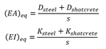
with
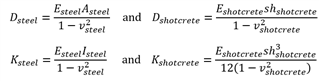
where:
- Esteel is the Young’s modulus of the steel
- Asteel is the cross-sectional area of each steel set
- Isteel is the moment of inertia of each steel set
- vsteel is the Poisson’s ratio of the steel
- Eshotcrete is the Young’s modulus of the shotcrete
- hshotcrete is the thickness of the shotcrete
- vshotcrete is the Poisson’s ratio of the shotcrete
- s is the spacing between two consecutive steel sets
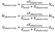
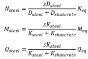
The bending moments, shear forces and axial thrusts are calculated for the equivalent composite. In order to consider the behavior of the steel sets and the shotcrete separately, it is necessary to redistribute these thrusts and moments back onto the individual support elements. The equations for the redistribution of the moment Meq, axial thrust Neq and shear forces Qeq induced in any one of the beam elements representing the equivalent shell are (thin beam solution only):
For shotcrete:
For steel sets:
Capacity diagrams
The graphical representation of induced axial thrust and bending moment on a tunnel lining plotted together with the corresponding ‘envelope of failure’ (i.e. the maximum values of axial thrust and bending moment that the support is allowed to withstand) is referred to as thrust–bending moment interaction. Similarly, the representation of axial thrust and shear force on a tunnel lining, together with the corresponding failure envelope, is referred to as thrust—shear force interaction diagram. Both graphical representations are commonly referred to as support capacity diagrams in structural engineering and concrete design.
The construction of thrust–bending moment and thrust–shear force interaction diagrams also follow the original idea of Carranza-Torres and Diederichs (2009)
- Bending moment-Thrust capacity
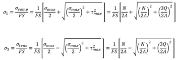
The maximum permissible compressive and tensile stresses induced in the lining for any considered factor of safety FS are given by:

where:
- N is the admissible thrust for the considered component (steel set or shotcrete)
- M is the admissible bending moment for the considered component (steel set or shotcrete)
- A is the area for the considered component (steel set or shotcrete)
- I is the inertia for the considered component (steel set or shotcrete)
- h is the section depth for the considered component (steel set or shotcrete)
- Shear force-Thrust capacity
where:
- N is the admissible thrust for the considered component (steel set or shotcrete)
- Q is the admissible shear force for the considered component (steel set or shotcrete)
- A is the area for the considered component (steel set or shotcrete)
References
- Carranza-Torres, C. and Diederichs, M. (2009) – “Mechanical analysis of circular liners with particular reference to composite supports. For example, liners consisting of shotcrete and steel sets”. Tunnelling and Underground Space Technology, Vol. 24, Elsevier, London, pp. 506–532.
Version
The script is tested with PLAXIS 2D CONNECT Edition V22 Update 1 and Python 3.8.
Disclaimer
Copyright (c) Plaxis bv. All rights reserved. Unless explicitly acquired and licensed from Licensor under another license, the contents of this file are subject to the Plaxis Public License ("PPL") Version 1.0, or subsequent versions as allowed by the PPL, and You may not copy or use this file in either source code or executable form, except in compliance with the terms and conditions of the PPL.
All software distributed under the PPL is provided strictly on an "AS IS" basis, WITHOUT WARRANTY OF ANY KIND, EITHER EXPRESS OR IMPLIED, AND LICENSOR HEREBY DISCLAIMS ALL SUCH WARRANTIES, INCLUDING WITHOUT LIMITATION, ANY WARRANTIES OF MERCHANTABILITY, FITNESS FOR A PARTICULAR PURPOSE, QUIET ENJOYMENT, OR NON-INFRINGEMENT. See the PPL for specific language governing rights and limitations under the PPL.