| |
Applies To |
|
|
| |
Product(s): |
WaterGEMS, WaterCAD, HAMMER |
|
| |
Version(s): |
CONNECT Edition, V8i |
|
| |
Area: |
Modeling |
|
| |
Original Author: |
Akshaya Niraula, Bentley Technical Support Group |
|
Problem
How can I simulate a constant headloss across a valve?
Solution
This can be done via a GPV (General Purpose Valve) or a PBV (Pressure Breaker Valve).
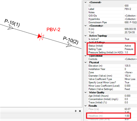
PBV
A Pressure breaker valve (PBV) creates a specified fixed headloss across the valve and is often used to model components that cannot be easily modeled using standard minor loss elements.
To induce a specific headloss (regardless of flow), select "hydraulic grade" as the "Setting Type" and enter the value in length units such as feet or meters of H2O. Or, select "pressure" as the "Setting Type", and enter a specific pressure loss. Note the calculated headloss (in the "Results" section of the properties) matching the headloss setting in the screenshot below.
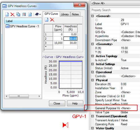
GPV
A GPV defines a rating table of flow versus headloss. For a constant headloss, enter a constant headloss value for the expected range of flow:
Transient Simulation Considerations
The PBV and GPV elements will not work the same during a transient simulation in HAMMER. HAMMER always uses the pair of initial flow and initial headloss through each valve element, to calculate a discharge coefficient which it uses during the transient simulation. This means that even if you use a PBV for the initial conditions, the headloss will vary during the transient simulation. To model a boundary condition at a constant hydraulic grade during the transient simulation, use the Periodic Head-Flow element.