| |
Applies To |
|
|
| |
Product(s): |
HAMMER |
|
| |
Version(s): |
10.00.xx.xx, 08.11.xx.xx |
|
| |
Area: |
Settings/Attributes |
|
| |
Original Author: |
Jesse Dringoli, Bentley Technical Support Group |
|
Problem
What is the purpose of the "Ratio of losses" attribute of a hydropneumatic tank or surge tank in HAMMER? How are headlosses determined through these tanks?
Problem Number: 34650
Solution
The headloss through the orifice connecting these tanks to the pipeline is determined by the "minor loss coefficient (outflow)" attribute (or "headloss coefficient for a surge tank). When the tank is draining (outflow), just this coefficient alone is used to determine the losses, based on the velocity through the orifice, using the standard headloss equation H = KV^2/(2g). When the tank is filling, the minor loss coefficient is multiplied by the value entered in the "ratio of losses" field to determine the inflow headloss.
Note that in HAMMER V8 XM (08.09.400.34) and greater, the minor loss coefficient was incorrectly labeled "minor loss coefficient (inflow)" for the hydropneumatic tank. In V8i and greater, it is correctly labeled "Minor loss coefficient (outflow)".
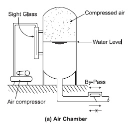
One reason for using a ratio of losses greater than 1.0 is to model a "differential orifice" such as in the diagram below. See linked article below for more.
Should the minor loss coefficient for a tank also include the K for head loss through the differential orifice or just the K value for the minor losses (i.e. fittings and contraction)?
This is a decision for the engineer to make, as there isn't one single way of modeling it.
Since the K that you enter corresponds to the velocity through the "diameter" that you enter, it would normally represent the losses through that opening only. If you need to model minor losses through fittings, bends, etc., you would probably want to enter those in the adjacent pipe if that pipe diameter is different from the diameter of the tank orifice, so that the correct velocity is used. Another option is you could account for them with an Orifice Between Pipes element, or even by lengthening the pipe to have an equivalent friction loss. It depends on what you feel is most appropriate for the situation.
If you wanted to lump all of your minor losses into that single K factor, you would need to come up with a K that gives the appropriate headloss for the velocity that would occur through the "diameter" field that you entered. In the case of a differential orifice, you could set the diameter and K to represent the losses through the larger size pipe with the check valve, account for losses through the check valve, pipe, bends, fittings and tank inlet. Then, you would need to figure out how much head loss you would get for the reverse flow, when flow travels through the bypass. From that, you would calculate what the ratio of losses is. That way when tank outflow occurs, the head loss through the tank assembly accounts for all losses from the tank to the main line. Then when tank inflow occurs, the head loss from the main line to the tank would account for all those same losses, plus the additional loss from going through the bypass.
If you didn't have a differential orifice or any significant bends/fittings, you would set the diameter equal to the tank inlet orifice diameter and set the K to represent the losses through that opening. You could then explicitly model the pipe going from the main line to the tank and enter a friction factor to account for those losses, or place the tank inline with the main line and increase the K factor a bit to account for those losses. Note that the inclusion of the lateral pipe may be significant on the transient results, as the pressure in the tank would need to accelerate that volume of water during a transient event.
See Also
Modeling Reference - Hydropneumatic Tanks
Determining the Headloss Coefficient for a hydropneumatic tank or surge tank