| |
Applies To |
|
|
| |
Product(s): |
WaterGEMS, WaterCAD, HAMMER |
|
| |
Version(s): |
V8i, CONNECT Edition |
|
| |
Area: |
Output and Results |
|
| |
Original Author: |
Jesse Dringoli, Bentley Technical Support Group |
|
Problem
What does the following user notification mean? "FCV caused Ill-conditioning" (this may also occur with a PRV or PSV)
What causes a flow control valve to become ill conditioned?
Problem ID#: 48411
Solution
The "ill conditioning" user notification (ill conditioned matrix) almost always indicates that the valve has been incorrectly configured. It can occur with an FCV, PRV or PSV. There are cases where no matter what pressure setting, hydraulic grade value, or flow control setting that you enter into the FCV/PSV/PRV that it can't possible work.
Ill Conditioning for a FCV
For a FCV, typically this problem occurs when it is placed in such a way that there is no other path around it to supply downstream demands. For example, consider a case where you have an active FCV with a setting of 100 gpm, with a demand of 150 gpm downstream of it and no other path around that FCV to supply the demand. If that is the case make sure that it's possible the valve can actually control the pressure.
Ill Conditioning for a PRV or PSV
There are two main situations that can cause ill conditioning with a PRV or PSV.
PRV and PSV in series:
In some cases, you may need to model a PSV and PRV in series. When problems arise such as Ill-conditioning, the first thing to check is the make sure that the valves have the correct orientation and that their settings are such that it is physically possible to solve with the given network configuration (assumed boundary HGLs, assumed demands, etc). For example take a look at the elevations of the upstream and downstream boundary conditions (if there are no pumps) to see if it is physically possible for the valves to be able to achieve their setpoints given the already-present hydraulic grade. One simpler approach to modeling this would be to replace the PRV/PSV arrangement with a single PBV (Pressure Breaker Valve) and vary the headloss to see if it is possible for there to be a particular headloss (through the valving) that would achieve both desired setpoints.
If the valves are configured correctly and the ill-conditioned message persists, there are a couple of options available. First, there is a field in the calculation options that can be adjusted. Open the active calculation option in the Properties grid and finding the property field Damping Limit.
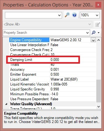
This value has a default of zero, but in difficult modeling cases involving valves, you can set this to a value that is 10 times the Accuracy you are using. For instance, if you are using an Accuracy of 0.001, you would set the Damping Limit to 0.01.
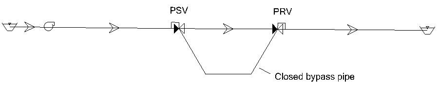
If this does not help, you may need to place a bypass "leak" pipe around the valves and set the status to Closed. This is a modelers trick that helps preserve network conditioning. For example:
Single PRV or PSV with downstream demands:
An ill conditioned network can also occur with a single PRV or PSV, when it is configured in such a way that it cannot solve the network hydraulic equations. Take the setup below.

In this model PSV1 is set to control the pressure at J3 to 15 psi and there is a 2500 gpm demand downstream of the PSV at the Outflow to the canal. In this situation the pump(s) head is fixed because the pump(s) works based on the head v. flow pump curve that you have defined for them. This poses a problem because that means the pressure at junction J3 is being controlled by the pump head and flow because the pumps always have to operate at fixed point on their curve to meet the 2500 gpm demand that is set on the downstream junction, so there is nothing the PSV can do to control the pressure. What you need to do in order to control the flow at the outflow to the canal junction is have some type of pressure dependent demand element there that allows the flow to change based on the pressure available. The element that you'd use for that would be the discharge to atmosphere (D2A) element, which is located right below check valve element on the layout toolbar. All you have to do for the D2A element is enter the elevation, which should be the same as the outflow to the canal elevation and enter the flow (typical) and pressure drop (typical). For example, if you entered a pressure drop of 10 psi and flow of 2500 gpm you would see where the PSV could function and allow the pumps to add more head to the system. The typical pressure drop and typical flow are used to automatically calculate a flow emitter (orifice) coefficient, which will be used during the simulation to calculate outflows. Basically, the values you entered are used in the orifice equation to determine the size of the orifice. If necessary you can use the orifice equation to do the math to figure out the typical pressure and typical flow you'd have to enter to simulate a given orifice size.
Q = C A (2 g P)^0.5
Q - Discharge (cfs, cms)
C - A 'discharge coefficient' (distinct from CV used elsewhere in HAMMER) which will be computed based on the typical flow/pressure
A - The cross-sectional area of the opening (ft, m)
g - gravitational acceleration
P - Pressure head (ft, m)
As you can see, once the "C" is calculated from the initial head/flow, the program can solve for other flows, as the pressure head changes during the simulation.
Example Model
Here is an example model that covers all three above cases. Please log in first to download.
Ill Conditioning Example Model
See Also
Problems when using a flow control valve (FCV) downstream of a pump
Troubleshooting "Network Unbalanced" or "Cannot solve network hydraulic equations" user notification