| Product(s): |
StormCAD, SewerGEMS, CivilStorm, SewerCAD |
| Version(s): |
V8i SELECT Series 4 (08.11.04.54) and later |
| Area: |
Modeling |
Background
The ability to attach Digital Terrain Models and the Downstream Trace tool were introduced with the release of SELECTseries 4 ( available in version 08.11.04.54 and later).
NOTE : Terrain Models are currently supported in the stand-alone and MicroStation platforms only. It is not supported in AutoCAD integrated platform as this feature requires utilization of platform specific components, in which case platform compatibility can vary. In case of terrain models, overlaying of a terrain model involves the use of AutoCAD components, which are currently not supported. We are looking into possibility of performing the work required to incorporate Terrain Models into AutoCAD, sometime in the future. For now you may continue using stand-alone or MicroStation integrated platform for importing the terrain models and then open that model in AutoCAD integrated platform. You can also use Terrain Extractor to assign elevations.
Starting with the release of CONNECT Edition (version 10.00.00.40 and later) the contours can be displayed and the catchment delineation tool was added.
The following digital terrain model source types can be used.
- Bentley Terrain Models - these are terrain files created by the following Bentley products:
- InRoads (.dtm) - must be in MicroStation integrated mode
- GEOPAK (.tin)
- MX (.fil)
- Bentley DGN Terrain Models - must be in MicroStation integrated mode. Must be the active DGN file, reference DGNs currently not supported as of August, 2023.
- LandXML terrain models
- DXF Point and Contour files (starting with CONNECT Edition Update 2)
- ESRI Shapefiles (starting with CONNECT Edition Update 2)
Some uses of digital terrain models are:
- Dynamic Ground Elevation Updates (Moving nodes adjusts the elevations)
- Downstream Trace (Find natural water path)
- Catchment Delineation
- View terrain in profiles
- Enable constraint based design to consider cover along pipe length
- Import gutter cross sections
You can use terrain modeling and terrain modeling tools to automate elevation allocation. You can conveniently trace and display the surface water flow direction across any terrain, ensuring proper location of inlets and other drainage infrastructure.
Note that the primary use case for Terrain Models is for new models where you are laying out or importing new elements, which will then be assigned elevations based on the terrain model overlay. If you have existing elements in the model that you wish to assign elevations to, use the Terrain Extractor (TReX) tool instead.
To use the Terrain Model tool, go to View > Terrain Models. The following dialogue box will pop up.
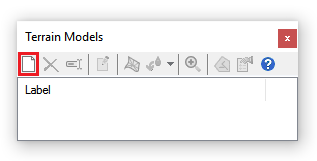
Click on the new button to import a terrain model. The dialogue box below will appear to select the terrain model source. Note that there is a boundary line color, also, as a boundary is drawn around the terrain model area.
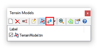
You can have several terrain models in a project, but only one can be active at a time.

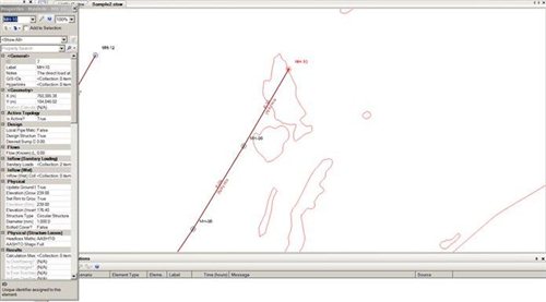
Here is an example of a terrain model's contours and boundary lines.

If you look at the MH-10 properties, you will see the ground elevation of 239.88.
If you move MH-10, the ground elevation will get updated by the elevations in the terrain model because the "Update Ground Elevation" is set to True.
Starting with the CONNECT Edition Update 2 release, you apply the ground elevation for selected nodes by right-clicking on an active terrain model and selecting “Apply Ground Elevation to Selected Nodes.” Any selected nodes within the boundaries of the terrain model will have its ground elevation updated if the option “Update Ground Elevation from Terrain Model?” is set to true.
NOTE:
When importing external data such as nodes, pipes etc. via ModelBuilder onto an already added "active" terrain model in the file, the Elevation (Ground) field (for manholes) won't be automatically updated even if "Update Ground Elevation from Terrain Model?" is set to "True". A defect was filed for this (#954248) for version 10.01.01.04. The issue has been fixed in version 10.01.01.04 by adding a new field "Apply Ground Elevations to Selected Nodes" for the Terrain Model which will also be available by default in future releases. Users can request a patch from the Technical Support team for this. The Technical Support team shall file a Service Request for this and share the patch with you. Patch is available for version 10.01.01.04 for all storm-sewer products viz. StormCAD, CivilStorm, StormCAD and SewerGEMS.
If there is a problem with requesting a patch, you can still apply the elevations to the manholes using the TReX tool.
What if I also have GPS survey elevations for some elements?
In some cases you may have survey elevation readings with higher accuracy, which should be protected from TReX updates. If you're using the Terrain Model feature instead of TReX, then you would set the node field "Update Ground Elevation from Terrain Model?" to "false" for nodes that have higher accuracy survey/GPS elevations. That way, the elevations for those nodes will keep the higher accuracy values (that you would populate manually from the survey readings, or from a ModelBuilder import) and the terrain model contour will not override.
Viewing the Z coordinate on mouse-over
With an active terrain model, the Z coordinate will be shown in the bottom right corner next to the X and Y. See: How to View Z Coordinate on Mouse-over with Terrain Models
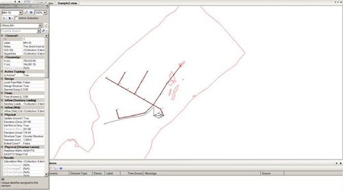
Downstream Trace
Another feature is the Downstream Trace (also known as water drop trace). You can pick points within the terrain model and it will trace downstream to the lowest point.
You will get the following dialogue box. You will need to put in the value for the option if you want to ignore any depressions less than a certain dimension.
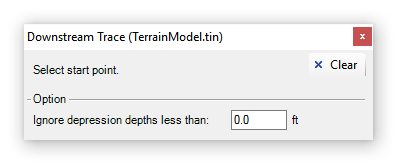
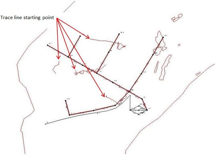
After you set the value, you can select a point in the model within the terrain boundary and the software will draw the trace lines.
Note: currently (as of 10.00.00.40) the downstream trace feature will not display the length or slope of the trace line. Enhancement 677454 was filed for the ability to do this in a future release. In the meantime if you need to see the length and slope for purposes of determining the time of concentration (Tc), you can trace over the line with a pipe, holding down the CTRL key to add bends, then look at the scaled length of that pipe. Elevations could be added to the end nodes to check the pipe's slope.
Viewing Contours for Terrain Models
See this short video to understand how you can view terrain model contours in plan view, and automatically populate node ground elevations.
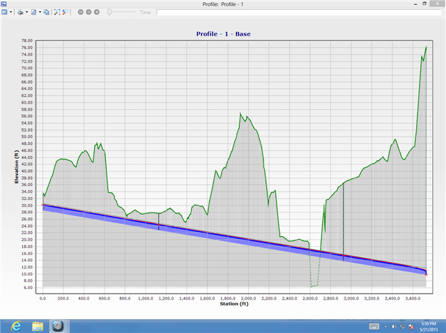
Viewing Terrain Models in Profiles
Starting with V8i SELECTseries 5 (and greater, including CONNECT Edition), profiles will display ground elevations as per the active terrain model:
Using Terrain Models to enable constraint based design to consider cover along the pipe length
Starting with V8i SELECTseries 5 of the Storm and Sewer products, if you have an active Terrain Model, ground elevations from that model may be used during a Design run to consider cover along the pipe's length. If you want to use this option check "Consider Cover Along Pipe Length?" as shown below.


See Also
Consuming ContextCapture production files within your hydraulic model
Using Catchment Delineation
How to View Z Coordinate on Mouse-over with Terrain Models