| |
Applies To |
|
|
| |
Product(s): |
WaterGEMS, WaterCAD, HAMMER, SewerGEMS, SewerCAD, StormCAD, CivilStorm, PondPack |
|
| |
Version(s): |
08.11.xx.xx, 10.xx.xx.xx |
|
| |
Area: |
Layout and Data Input |
|
| |
Original Author: |
Terry Foster, Bentley Technical Support Group |
|
Problem
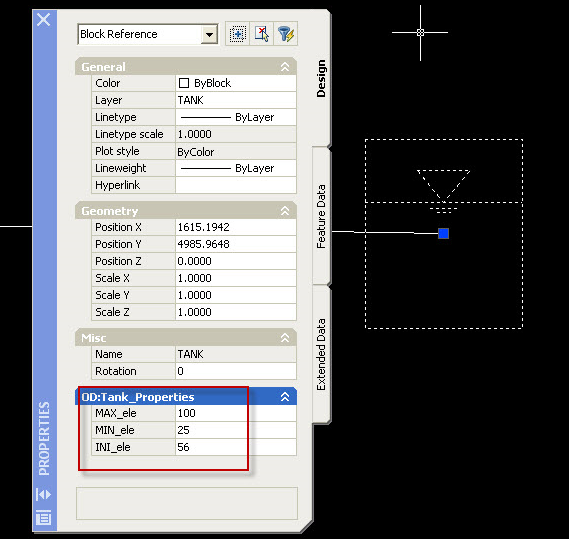
Additional attributes have been added to a CAD drawing (such as in Autodesk Map), for example tank MAX_ele, MIN_ele, INI_ele as seen in the below screenshot. These do not show up in ModelBuilder when trying to import as a DXF.
Solution
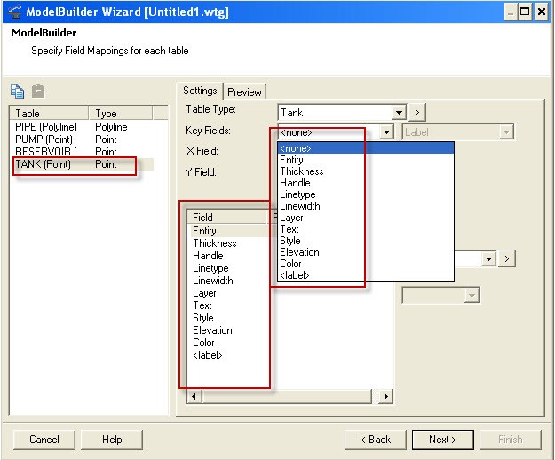
A .dxf file does not contain any of the extended AutoCAD Map data such as the elevations. The attributes available in ModelBuilder for a .dxf are those that are directly part of the point, polyline or polygons in the .dxf.
Usually the geometry of a network is of primary importance when importing a .dxf to avoid having to trace over it by hand. Often pipes of different diameters may be on separate layers, so prototypes are used to bring in each layer as a different diameter without mapping any attributes in ModelBuilder. See this article for more. Details such as node elevations, pump curves, demands, tank elevations, etc. are typically entered manually after the basic pipe and node information is imported from the .dxf file.
A workaround would be to export from AutoCAD Map to a Shapefile format, then import the Shapefile using ModelBuilder. (Check the AutoCAD Map help for details on how to export to Shapefiles.)
In some cases, you may have text entities located nearby the respective elements, with leader lines. There may be no reliable way to associate this text information to the actual element in order to import it in bulk with ModelBuilder.
See Also
A forum discussion about this issue
Importing an AutoCAD or MicroStation CAD file using ModelBuilder