| Applies To |
|
| Product(s): |
WaterGEMS, WaterCAD, SewerCAD |
| Version(s): |
CONNECT Edition, V8i |
| Area: |
Modeling |
| Original Author: |
Scott Kampa, Bentley Technical Support Group |
Problem
Is it possible to have a pump curve in the pump definitions use linear interpolation (go from point to point) instead of following a best-fit curve?
Solution
By default, the pump curves for WaterGEMS, WaterCAD, and SewerCAD follow a quadratic interpolation, giving the pump curve a smooth shape, as shown in the screenshot below. (note the coefficients shown below it)

At times, a user might want a multi-point pump curve to follow a linear interpolation so that the curve exactly follows the points in the table. This could be because the values in the pump curve may work better with a linear interpolation. For instance, there may be a large difference in flow for a small change in head. A user may also have pump data from a manufacturer that follows a linear interpolated pump curve and want the data in the model to match exactly.
In such cases, there is a setting in the calculation options where a user can set a multi-point pump curve to use linear interpolation. To use this, open the calculation option properties by going to Analysis > Calculation Options, then double-clicking the active calculation option. In WaterGEMS and WaterCAD, find the section called Hydraulics and change the setting for the attribute "Use Linear Interpolation for Multipoint Pump Curves?" to "True". In SewerCAD, the same attribute can be found in the section called Pressure Hydraulics.
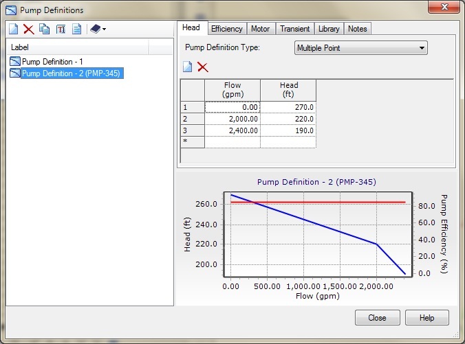
It is important to note that if "Use linear interpolation for multipoint pump curve?" is set to False the software not only interpolates between the points you have defined on your curve, but also extrapolates points past the largest flow point you have defined until it reaches the point for the zero head. If the option for "Use linear interpolation for multipoint pump curve?" is set to True, then the software only reads the points that you have defined in your multiple point pump curve. This can be easily identified by setting the option in the calculations then accessing the pump definitions. Once you look at the pump definition notice the graph in the lower right portion of the window. When the option for "Use Linear Interpolation for Multipoint Pump Curves?" is set to False, you'll see the zero head point on the far right of the x-axis on the graph. When you have the option set to True, you will see the last point on the x-axis stop at the last point you have defined.

Note: This only works for multi-point curves and not for three-point or one-point curves.
If you are using SewerGEMS, the pump definition only follows linear interpolation, with both the Implicit and Explicit solver. However, the appearance of the pump curve uses quadratic interpolation. If a user wants to see (for reporting purposes) the actual linear interpolation of the pump curve and has SewerGEMS SELECTseries 3 and later, there is an indirect way to change the appearance of the curves. To do this, first change the Active Numerical Solver in the calculation options from "Implicit" or "Explicit" to "GVF-Convex (SewerCAD)". The SewerCAD calculation option properties will then be available, including the attribute "Use Linear Interpolation for Multipoint Pump Curves". Change the setting of this property to "True", then change the Active Numerical Solver back to "Implicit" or "Explicit". The multi-point pump curve will not follow linear interpolation.
With linear interpolation set, the pump curve will look like the screenshot below: