| |
Applies To |
|
|
| |
Product(s): |
WaterGEMS, SewerGEMS, CivilStorm, StormCAD, PondPack, SewerCAD, HAMMER, WaterCAD |
|
| |
Version(s): |
CONNECT Edition, V8i |
|
| |
Area: |
Output and Reporting |
|
| |
Original Author: |
Mark Pachlhofer, Bentley Technical Support Group |
|
Problem
How do you create a free form annotation for Element Symbology (model plan view) or Engineering Profiles?
Background
The "Free Form" annotation option gives the user more control when setting up annotations of labels, attributes and results. You can set up multiple lines of annotations and input prefix/suffice characters as part of the annotation. So, it is a powerful tool for quickly visualizing what is happening at a given element. Free Form annotations can be configured for Element Symbology (for the drawing pane) and in Engineering Profiles.
Solution
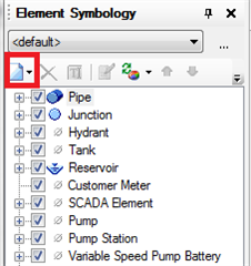
In Element Symbology
1) Highlight one of the elements you want to annotate by clicking on it and then click the new button (see red box) and choose 'New Annotation'.
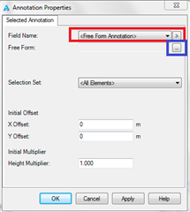
2) Free Form Annotation is selected by default in the annotation properties dialog box (see the red box). Click the ellipsis button (blue box) to open the free form annotation window as seen in step 4 above.
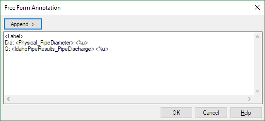
3) Use the '>' button to select the annotations you want to add, press Enter to go to a new line, and enter custom text as needed. In the example below for Pipes, the freeform annotation will show the pipe label, with the diameter under it with a prefix of "Dia", then the flow under that with the prefix of "Q:"
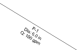
You can then select the group of annotations as one item to move and rotate as needed.
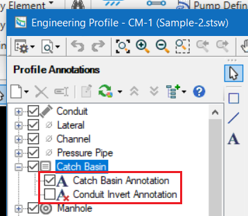
For an Engineering Profile
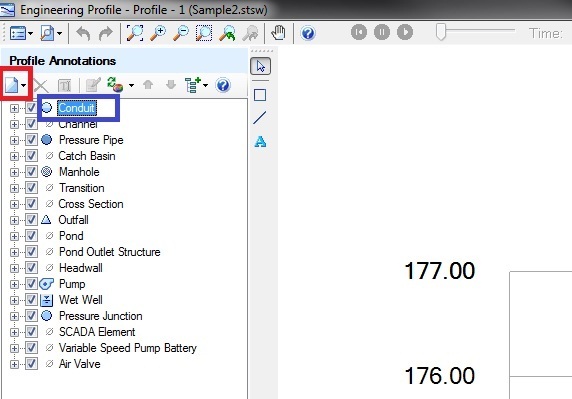
1) Locate the profile annotations window on the left side
2) Highlight one of the elements you want to annotate by clicking on it (see blue box) and then click the new button (see red box)
3) First click the new button to create the new annotation (red box). Next leave the 'Field Name' as <Free Form Annotation> (blue box) and click the ellipsis button next to the line below that (green box). This opens the free form annotation window.
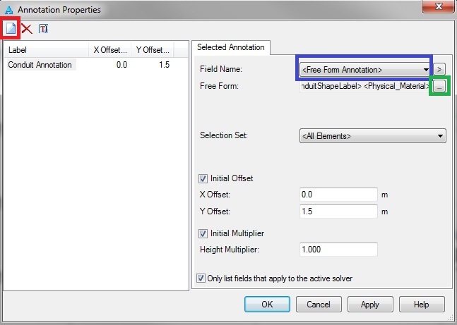
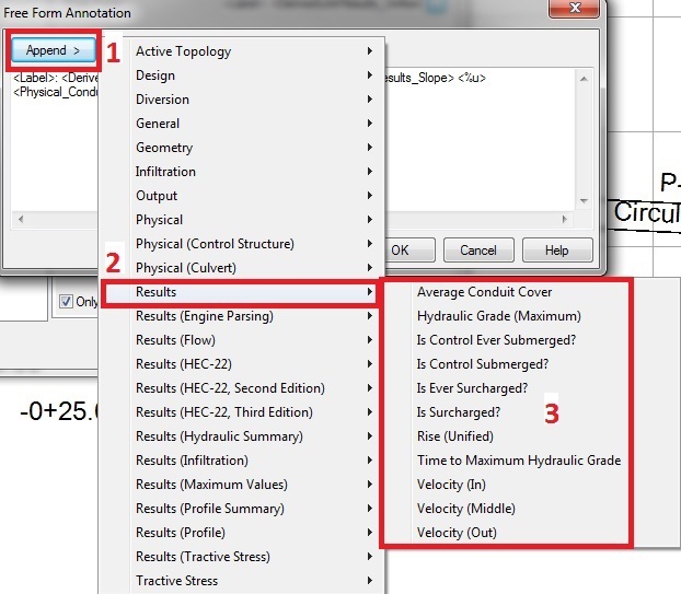
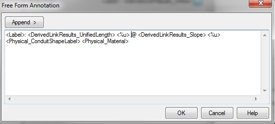
4) Now click the 'Append > ' button and choose the different properties for how you want to create your label. How you layout your label is how it will look on the drawing area. You can choose to stack you labels, lay them out linearly, and include other prefixes, suffixes, characters, or words. Please see the screen shot below.
Notice that you physically enter the spaces and the line breaks. This allows the annotation to look exactly how you have entered it on the drawing area. <%u> is the key code that allows that units to be displayed for a given property.
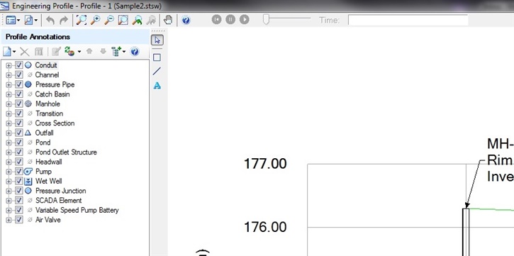
Here is what the annotation looks like in the profile:

After the annotation is placed you also have the ability to left click on it and drag it to any location you want. The locations can also be preset on the annotation properties that can be seen in the screen shot below step 3.
Managing Leader Lines and arrows
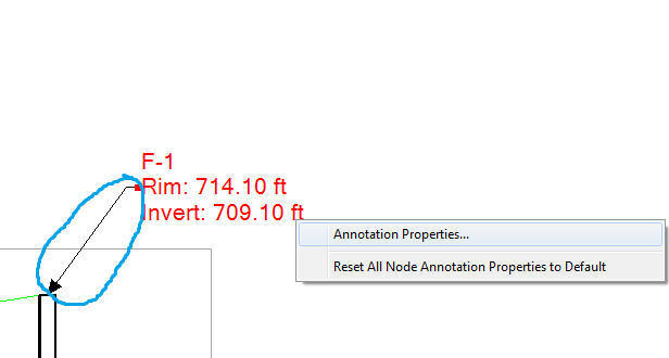
You also have the ability to add a leader line to an engineering profile, which is the line with the arrow that is seen in the screen shot below in the blue circle. To place it right click on the annotation in the engineering profile drawing pane and select "Annotation Properties" from the menu. When the Annotation Properties window opens click the check boxes for "Show Leader Line" and/or "Show Leader Arrow" (see screen shot below). These check boxes can be used to turn the leader line and/or arrow on or off.
Note: If you do not want the annotation at all, you can toggle it off using the check box on the left side of the Engineering Profiles, or you can delete the annotation altogether.
Annotation Properties Dialog is show below:

Turning on/off annotations: