| |
Applies To |
|
|
| |
Product(s): |
WaterGEMS, SewerGEMS, CivilStorm, StormCAD, PondPack, SewerCAD, HAMMER, WaterCAD |
|
| |
Version(s): |
08.11.XX.XX, CONNECT Edition |
|
| |
Area: |
Modeling |
|
| |
Original Author: |
Mark Pachlhofer, Bentley Technical Support Group |
|
Problem
How do I model devices, control structures, or other elements the software might not explicitly provide when modeling my system?
Background
Occasionally, when modeling you have an element in the real world that you can't figure out exactly how to model because there isn't a specific element or feature for it. The process of thinking and questions provided below should help you to come up with a creative workaround to help resolve this.
Solution
1) Think about exactly what the element does hydraulically in the real world and how it functions. What is the purpose of it? How does this relate to the end goal of this model? (the "answer" you need from the model)
2) What exactly is it that you need to learn from your model? What is the goal of creating this model?
3) Do you have the appropriate solver selected for the end goal of your model?
Example: If you are trying to account for flooding in your system you wouldn't want to use the GVF Convex (SewerCAD) solver you would want to use the Implicit (SewerGEMS) or Explicit (SWMM) solver, which can account for this. It's important to choose the correct solver because each one functions differently and there may be different properties and functionality for the modeling elements.
4) Place a few elements in a sample model project that you think might be able to resolve the problem.
5) Open the properties of each one and examine them. Is there anything that looks like it might have some of the properties that you are looking for or could use to simulate what you have in the real world?
6) Create a sample model with as few elements as possible to help you focus on modeling the workaround and test it here.
7) Once you get the workaround functioning in a sample model try to add it to your model and make adjustments as necessary.
8) If you're having trouble getting the workaround to function make a change that seems reasonable and pay close attention to how the results changed (reacted). Take what you have learned from the results and make an educated decision as to how you might resolve the issue. This make a take a few tries in order to understand what is happening. The key here is don't be afraid to make changes and try things. If you make a mistake it can always be undone using the "undo" function from the Edit menu.
9) Consider a sensitivity analysis if unsure - try a range of values, or multiple approaches, then see if it has a significant impact on the results that you need to get from the model.
The process in action
Case example 1: Clean Out
Problem
I'd like to model a clean out on a force main, but I don't see a clean out element. How do I model this? (Using SewerCAD)
Process
1) Think about exactly what the element does hydraulically in the real world and how it functions. What is the purpose of it? How does this relate to the end goal of this model?
The element just needs to be represented in my model and I don't believe there is any significant effect caused by it hydraulically, but I'd still like to represent it as accurately as possible.
What you should be thinking
In this case I may not need to model the clean out at all, but I should take a look at a few options just to make sure my model is accurate. There is only one solver in SewerCAD, so I don't have to worry about question 3 and we're using a very general goal for this model, which is to just model what we have as accurately as possible. Given the aforementioned information I can skip to step 4 to start looking at the different model elements I might want to consider.
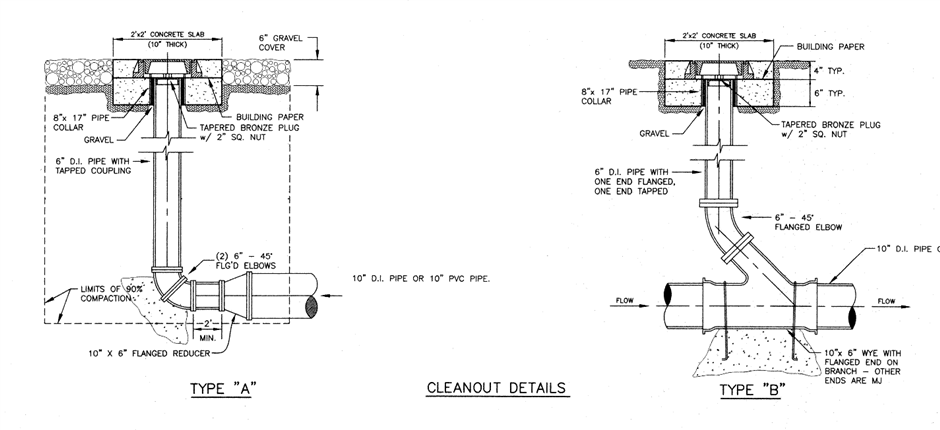
2) I know that my clean outs can look like either of these setups in the screen shot below, so I'm going to layout a manhole, pressure junction, transition, and a pressure pipe to examine the properties of each of those elements.
Manhole
Contains a rim elevation, invert elevation, structure type (circular, box, transition), diameter, the option to have a bolted cover, a place where sanitary or wet loads can be entered, and a structure loss
Junction
Elevation and a place to enter sanitary or wet loads
Transition
Invert elevation, crown elevation, transition length, and structure loss
Pressure Pipe
Diameter, material, roughness coefficient, invert start, invert stop, user defined length, specify minor loss, minor loss coefficient
Based on this information I have decided that I can probably come up with a few configurations to try out.

In the first configuration at the top J-3 represents the top or cap of the clean out and is at a higher elevation that J-2 and J-1. There are also minor losses entered on one of the pipes that represents the 45degree bend.
The second and third configurations are similar. The manhole or transition would represent the length or depth of the clean out. I'd do this by making the rim (crown) elevation higher than the invert elevation. The advantages that the manhole configuration has over the transition are that can be defined are the diameter of the clean out pipe via the manhole diameter and the ability to define a bolted cover. The transition element doesn't have these features, so the third configuration probably won't work.
The forth configuration is sort of a combination of the first and second, but uses a transition at the connection point between the clean out pipe and the carrier pipe. The only real differences between this option and the first one is that you can add a transition length to the element and define any headloss via one of the methods.
3) The next steps in the process are 6 and 7. You could put a reservoir on one end and see how this configuration works for you in a sample model, but since this is a simple case you might just want to add one of these at a time to your model, compute the model, and make an engineering judgment as to which you think best models the results you're expecting. This would also be a great place to take advantage of the power of the scenarios and alternatives. You could make 3 different scenarios and try out each the 3 configurations then compare their results.
Case Example 2
Problem
I am trying to analyze a water system with one or more of the following types of devices, which are not explicitly available as elements:
- Water meters
- Post indicator valves
- Backflow preventers
- Heat exchanger
- Sand filter or cartridge filter
- Rationing Control Valve (RCV)
Process
How do these devices work hydraulically?
A water meter / flow meter doesn't really do much hydraulically except for provide a minor loss, so it can be modeled as a minor loss on a pipe. There is a property titled "Specify Minor Loss?" that when set to 'True' allows you to enter the entire minor loss coefficient if you know it. If the field is set to 'False' it will reveal a new collection property that will allow you to enter all the minor losses that you might have on your pipe by quantity and type (30 degree bend, 90 degree bend, contraction, expansion, tee, etc...). Once you enter all the types of losses and the quantity of each the K values will be totaled for you and entered in the 'minor loss coefficient(derived)' property upon closing the minor loss collection dialog box. If you need to model a more complex flow vs. headloss relationship, use a GPV node element with GPV headloss curve.
A post indicator valve is just an assembly that is used to open or close the water supply to fire protection for large buildings. If you were to look at all the elements and their properties you'd find this is most closely related to a isolation valve that has one of two statuses: Open or Closed. Iso Valves also have properties that allow a user to the diameter, minor loss coefficients associated with the valve, an elevation, date installed, and whether the valve us operable. If the valve is operable it allows the program to segment pipes in other models based on the location the iso valve is placed on the pipe.
A backflow preventer device prevents water from a potentially contaminated or polluted source to flow back into the system during times of low pressure. It can be modeled by using a general purpose valve (GPV). GPV's allow the user to choose a type (globe, ball, butterfly, gate, needle, or user defined) and apply a flow vs. headloss curve to simulate many valve types that aren't explicitly defined like the pressure sustaining valve (PSV), pressure reducing valve (PRV), throttle control valve (TCV), flow control valve (FCV), etc....
A heat exchanger acts as a headloss between the upstream and downstream side, as water can pass through multiple internal parallel pipes. Either model them explicitly as parallel pipes (use bends so the separate pipes can be seen in plan view), or get a curve/table from the manufacturer of head loss (pressure drop) vs. flow and use a General Purpose Valve (GPV) element to simulate the head loss. If you have a flow meter and a tap to measure pressure at each end, you can generate your own curve.
A filter hydraulically acts as a headloss, which could be approximated either as a minor loss coefficient on a pipe, or a GPV headloss curve. (table of flow vs. headloss)
A pressurized aeration tank likely experiences very little head loss unless there are baffles and can be modeled with a GPV headloss curve. (table of flow vs. headloss). Also consider if there may some head loss though the valves that can control flow or isolate the vessel (you would need to get data on the valves used) Consider talking to the vessel manufacturer to check if they have any data on head loss vs. flow through their vessels.
A rationing control valve (RCV) is usually associated with "hand pump" operation. The valve operates by hand allowing a fixed quantity of fluid to be "rationed" and extracted out. If this needs to be modeled when modeling standposts or hand pump operation on field an FCV can be used to "control" the flow downstream if a fixed outflow is expected. Alternatively, if the "rationing" is based on a fixed headloss applied at the valve, you can try using a TCV. See more details here.
An energy dissipation structure used to slow flow velocity, such as "chute blocks" or "baffle blocks". In the context of a stormwater system, this could be modeled by adjusting the roughness coefficient of the conduit or channel, or by using conduit control structures or a minor loss coefficient on the conduit or channel.
NOTE: For a transient simulation with HAMMER, a GPV headloss curve is not used explicitly and a minor loss coefficient is lumped together with friction losses to determine the overall friction factor for the pipe. Devices such as the above can also be modeled with the Orifice Between Pipes element in HAMMER, which essentially models a discharge coefficient at a discrete point, established by way of a pair of flow and head drop (which you could determine from a typical flow through your device). Transient energy can be dampened from the headloss across the device.