| Product(s): |
WaterGEMS, HAMMER, WaterCAD |
|
| Version(s): |
10.XX.XX.XX, 08.11.XX.XX |
|
| Area: |
Modeling |
|
Problem
How do I model parallel fixed head (target head) variable speed pumps that are controlled by flow in a downstream pipe?
OR
How do I resolve the user notification, "Variable speed pumps not in parallel cannot be controlled by the same control node"?
Background
Parallel variable speed pumps have special rules that apply and unless you make some specific changes to your model to workaround these rules your pumps will not work as you'd like them to.
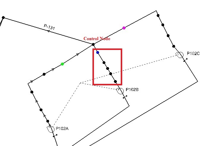
In the screen shot below the following model was originally set up where all the pumps had a single downstream junction, the black one immediately downstream of the colored junctions, which functioned as the single node the VSPs were controlled based on.
The controls used for the model below are as follows:
IF P-131 Flow < 25.000 L/s THEN P102A Pump Status = On
IF P-131 Flow >= 25.000 L/s And P-131 Flow <= 50.000 L/s THEN P102B Pump Status = On
IF P-131 Flow > 50.000 L/s THEN P102C Pump Status = On
Solution
Option 1
Setup the VSP's having a single upstream and downstream element. For the example, it would look something like this;
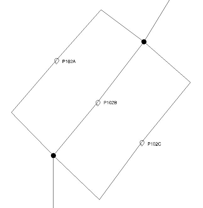
You can notice that all the VSP's have the same start and stop node thus making them effectively parallel.
Note: This setup can be used if the control node (to control the VSP's) is away from the parallel VSP's setup. Generally this is some critical junction in the network whose head controls the operation of the parallel VSP's.
Option 2
1) Add 5 junctions between your pumps and the downstream control node. The software then interprets each of these VSPs separately, which is why we have step two. If we didn't have step two then the software would generate a red user notification that would prevent you from running the model. The user notification reads, "Not parallel variable speed pumps cannot be controlled by the same control node".
2) The fifth junction (green, blue, and pink all each line) that you place will be the new control node for the upstream pump, so make sure to set it appropriately in the pump properties for the control node.
See Also
User Notification "More than one VSPB cannot control the same control node"
User notification is generated after computing a model with parallel variable speed pumps (VSPs) about the pumps or "Network Unbalanced" or "Cannot compute network hydraulics"