| Product: |
HAMMER |
| Version(s): |
V8i, CONNECT Edition |
| Area: |
Output and Reporting |
Problem
What determines the number of profile increments and the % interval when viewing a pipe profile with the Transient Results Viewer in Bentley Hammer?
Solution
The number of transient profile increments, and the % of the intervals, is a function of Time Step, Wave Speed and Profile Section Pipe Length. The following equations show the relation.
Equations:
A) Profile Section Pipe Length = Wave Speed * Transient Time Step
B) # of Increments = Pipe Length in Profile / (Wave Speed * Transient Time Step)
C) Interval % = 100% / # of Increments
The transient solver calculates and reports results at various points along the pipeline, based on where a wave ends up at the end of each calculation time step. In order to do this, it sometimes needs to artificially adjust the length of the pipes (or adjust the wave speed if the user chooses that instead of length). You can read more about it in the wiki article "Understanding length/wave speed adjustments and their impact on results".
Equation B uses the adjusted pipe length (not the original pipe length).
Note: the total station length as seen in profile view should match the total original pipe length, If it does not, or if you find that the length changes wrongly as the timestep is changed, you may have encountered a known issue (defect #1071822) which has been resolved in a cumulative patch set for HAMMER version 10.02.03.06 (and in future versions of HAMMER). Contact Technical Support for help, or upgrade to a newer version when available.
Examples
Let’s take a look at two examples.
(Default directory is C:\Program Files (x86)\Bentley\HAMMER8\Samples)
Example 1: Sample1.wtg
This is an basic model of a reservoir providing flow through a pipe and discharging to the atmosphere.
Pipe Length = 1000m
Wave Speed = 1000m/s
Transient Time Step = 0.066667s
(Analysis > Transient Time Step Options)
(Equation A)
In 0.066667s, a wave will travel exactly 66.667m through the pipe.
Profile Section Pipe Length = Wave Speed * Transient Time Step
Profile Section Pipe Length = 1000m/s * 0.066667s
Profile Section Pipe Length = 66.667m
Since the Pipe Length 1000m is a multiple of the Profile Section Pipe Length 66.667m, HAMMER doesn’t need to adjust the Pipe Length.
(Equation B)
# of Increments = Pipe Length / Profile Section Pipe Length
# of Increments = 1000m/66.667m
# of Increments = 15
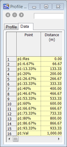
If you look at the data tab of the profile of the single pipe in the Transient Results Viewer, you’ll see 16 rows (15 increments).
(Equation C)
Interval % = 100% / # of Increments
Interval % = 100% / 15
Interval % = 6.6667%
Example 2: Hydropneumatic_Tank_Example.wtg
Now let's take a look at pipe P-7.
Pipe Length = 200m
Wave Speed = 1200m/s
Transient Time Step = 0.01s
(Equation A)
Profile Section Pipe Length = Wave Speed * Transient Time Step
Profile Section Pipe Length = 1200m/s * 0.01s
Profile Section Pipe Length = 12m
Since the 200m Pipe Length isn’t a multiple of 12, HAMMER needs to adjust it. If you compute the model, open the properties grid for pipe P-7 and look at the field called “Length Adjustment” in the “Results (Transient)” section you’ll see a value of 4.00 m. Add this to the original length of 200 m to get the adjusted length of 204 m, which is a multiple of 12.
(Equation B)
# of Increments = Pipe Length / Profile Section Pipe Length
# of Increments = 204m / 12m
# of Increments = 17
If you make a profile covering only this one pipe, compute the model and look at the data tab of that profile in the transient results viewer, you’ll see 18 rows (17 increments).
(Equation C)
Interval % = 100% / # of Increments
Interval % = 100% / 17
Interval % = 5.88%
You should be able to follow this logic in any model. Of course, it gets more complicated in a profile with multiple pipes with different wave speed, since you’d have to figure each one out individually to get the increment.
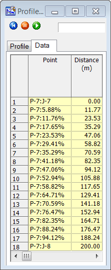
The distance in the data tab increases by 11.77m each interval because it is dividing the original 200m pipe length into 17 sections.
See Also
Understanding length/wave speed adjustments and their impact on results
Bentley Hammer Help Article - Time Step and Computational Reach Length