| |
Product(s): |
WaterGEMS, WaterCAD, HAMMER, SewerGEMS, SewerCAD, StormCAD, CivilStorm |
|
| |
Version(s): |
V8i, CONNECT Edition |
|
| |
Area: |
Modeling |
|
Problem
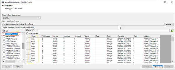
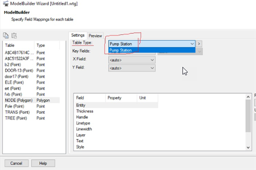
Why does ModelBuilder show my layer as "(Polygon)" when it should contain polylines (pipes)? Why do my line or point elements only have "pump station" as the table type to map to in ModelBuilder? (or catchments in the storm and sewer products)
Solution
If ModelBuilder shows "(Polygon)" after the layer name in the first step, this is an indication that the layers in your file are of the polygon shape type. In WaterCAD, WaterGEMS and HAMMER, you will then only see the pump station element type show up in the field mapping step, since that is currently the only polygon element type.
If you actually have pipes or junctions (nodes/points) in the layer in question, this may occur if a custom element or shape is included instead of the standard polyline or point type. For example if the drafter included a symbol (like a circle or something else) at the ends of the lines that represent pipes, as part of the single entity representing the pipe/line. If the element is removed from the end of the line or polyline, the line element will be recognized correctly by ModelBuilder.
Also check to make sure that your pipes in the source file are indeed polylines, and not for example polygons outlining the pipes. You can use the identify/properties function in MicroStation, AutoCAD or ArcMap to identify the entity type, then use available tools to convert or "explode" the polygons into individual polylines.
Furthermore, check to ensure that the lines are not closed polylines. If so, you can use the AutoCAD PEdit command to Open a polygon so it will be seen as a polyline.
In the case of points that are not recognized as junctions/manholes, make sure they are point features in the CAD drawing and not polygon shapes (like a circle). In that case you can use VLX file that you can add to Autocad and then you can convert circle to point by command. The command C2P converts selected circles to points.
If your network is small, you can try adding it as a background layer, press Zoom Extents, then lay out elements manually by tracing over the background DXF. Adding the DXF as a background may also reveal which parts are missing (potentially due to one of the reasons above)
Lastly, you may be seeing the "polygon" layer show up because of actual (real) polygons in the source file, and the issue may be that the polylines are not a supported polyline type, and so they do not show up in ModelBuilder. See: DXF or DGN layers missing in ModelBuilder
See Also
Building a Model with ModelBuilder
DXF or DGN layers missing in ModelBuilder
How the list of layers in Modelbuilder is determined for a DXF file with blocks