| |
Product(s): |
WaterGEMS, WaterCAD |
|
| |
Version(s): |
CONNECT Edition, V8i |
|
| |
Area: |
General |
|
Problem
How is an Orifice Between Pipes element used during a steady state or EPS in WaterCAD or WaterGEMS?

Solution
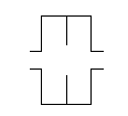
The Orifice between Pipes Element can be used in WaterCAD, WaterGEMS and HAMMER. Generally, This element represents a fixed-diameter orifice which can be used to model various devices and structures that induce a headloss, for example choke stations on high-head pipelines.
It is essentially a different way of specifying a headloss; a pair of flow and head drop. It is traditionally used for transient simulations in HAMMER to concentrate headloss at a discrete point, but will also calculate a headloss during a steady state or EPS in WaterCAD and WaterGEMS.
You can find this element in the Layout tap of the Ribbon Interface, then going to Transient > Orifice between Pipes. This is a node element that is included at the ends of the pipe. Once the element is in place, open the properties. You will need to include an elevation and a typical flow and typical pressure drop. The typical flow and typical pressure drop can be found using the orifice equation:
Q = C A (2 g P)^0.5
Q - Discharge (cfs, cms)
C - A 'discharge coefficient' (distinct from CV used elsewhere in HAMMER) which will be computed based on the typical flow/pressure
A - The cross-sectional area of the opening (ft, m)
g - gravitational acceleration
P - Pressure head (ft, m)
As an example, you could pick a typical flow and use this to solve the orifice equation for pressure. These input properties are used during calculation. The steady state/EPS solver calculates the CA value and respectively uses this for any dynamic change between the Q and P. There is no reason to need to enter the C or A values.
A Note on Temperature / Viscosity / Specific Gravity
If you need to change the fluid properties in the steady state/EPS calculation options (for example a different temperature, resulting in a different viscosity), it may be best to use the General purpose Valve (GPV) element instead of the orifice to ensure that the change is properly accounted for (reference defect # 978770). A GPV uses a user-entered rating table of flow versus headloss. If needed, you can use the orifice equation to calculate a rating table, which you can then enter in the GPV headloss curve.
The GPV will also provide finer control over the flow versus headloss relationship, enabling you to model any type of device that may not necessarily follow the orifice equation relationship. For example a screen, filter or heat exchange.
See Also
When using the orifice between pipes elements is it possible to enter the diameter instead of the typical flow and typical pressure drop?
