| |
Applies To |
|
|
| |
Product(s): |
HAMMER |
|
| |
Version(s): |
08.11.XX.XX and higher |
|
| |
Original Author: |
Mark Pachlhofer, Bentley Technical Support Group |
|
Problem
How do I model a pump shut down (pump power failure) transient event?
Solution
Shut down after time delay
The traditional method of simulating a pump shutdown transient event is to use the Shut After Time Delay transient pump type. This assumes that the applied electrical torque drops to zero at the time that you specify for the shutdown. For more on the assumptions, check the article in the "See Also" section at the bottom of this page.
Here are the steps to configure a pump shutdown event in HAMMER:
1) Set the pump Status (Initial) to 'On.'
2) In the Transient (Operational) section of the pump properties set the Pump Type (Transient) to 'Shut Down After Time Delay.'
3) Set the Time (Delay until Shut Down) property. The time you enter is the time at which the power to the pump motor is shut off. It should also be noted that a linear closure is assumed for this case.
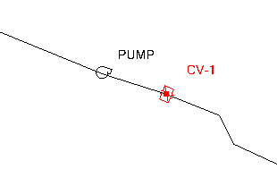
4) Set the Pump Valve Type to "check valve" or "control valve" depending if the pump has one of these type of valves. If your pump has a control valve you'll need to enter the time it takes for the valve to close. This is the time taken for the pump discharge control valve to close after the transient simulation begins, not from when the pump shut down begins. The check valve assumes instant closure on the first detection of reverse flow. If you want neither a control valve nor a check valve, set the Pump Valve Type to Control valve and enter a large number, such as 99999 seconds. If you want to control the closure time of the check valve use the steps from the last sentence then insert a check valve node element from your layout toolbar just downstream of the pump. See screenshot below:
Note that the pump check valve will not re-open if forward-flow occurs. So, if a reopen is anticipated to occur, you should instead model the check valve with the check valve node element. To do this, enter a closure time of 9999 seconds to model neither a valve nor a check valve, then insert check valve node elements adjacent to the pump(s).
Note: Unless you model this built-in valve, HAMMER does not assume that the pump is closed when the pump shuts down. Meaning, the 'Shut down after time delay' simulates a power failure to the pump impeller, which eventually may drop to zero rpm. However, flow can still pass through the zero-speed pump, unless you model a valve closure. If you want to see how the pump speed reacts to the pump shut down, you can view this in the Extended Node Data tab of the Transient Results Viewer.
Variable Speed/Torque pump shut down
Another option to model a pump shutdown transient event is to use the "Variable Speed/Torque" setting for the Pump Type (Transient). This would be used as part of a shutdown followed by startup. Or, it could be used to model a controlled shutdown, where the speed is ramped down. Here are the steps:
1) Set the pump Status (Initial) to 'On.'
2) Set the Pump Type (Transient) to 'Variable Speed/Torque.'
3) In the Time (Valve to Operate) property you enter the time to close the check valve or to open it if initial flow is zero. If the check valve allows flow only in one direction enter 0 (i.e., the pump has a built in check valve). To simulate a pump with no check valve or control valve enter a very large number like 99999 seconds so will not close in the model run time. If you enter a very small number like 0.1 seconds, the valve would close immediately after the start of the simulation, which would cause a transient response similar to a valve closure.
4) For the Control Variable properties you can choose either Speed or Torque. For more information on the difference between the variable speed and torque setting please refer to this wiki article. Here the default value is to control the speed of the impeller by using the pattern. If you want to control the pump using the torque control variable (so the momentum of the impeller is accounted for like with the 'Shut down after time delay' type) you have the option to do that too. For that approach, you will need to enter the nominal torque of the pump before it shuts down. The nominal torque is then multiplied by the operating rule pattern multiplier that will result in the torque values the numerical solver uses. To simulate the same behavior as the 'Shut after time delay,' you would have the multiplier in the pattern drop from 1.0 (full applied torque) to zero in one time step, at the time that you want the shut down to occur.
For a controlled shut down, you would control either the speed or the torque to gradually ramp down the pump, per the operating rule.
5) Define the operating rule the pump will shut down based on. Click the dropdown button in the entry box and choose <Edit...> to create a pattern.
6) Under the Operational (Transient, Pump) section, right-click to create a new pattern and set the starting multiplier equal to 1.000. In the section of the window under that enter the 'Time from Start,' which is the time the speed or torque starts to drop. In the multiplier column enter 0 for when the speed or torque is zero. If you have the pump shut down between time steps 5 and 10 seconds for example it will gradually shut down over that period.
Modeling a pump startup followed by shutdown, or shutdown followed by startup
The variable speed transient pump type would be used to model both a shutdown and startup in the same simulation. See more here:
Modeling a pump startup and shutdown transient event in the same simulation
A Note on Pump-Turbines
HAMMER currently does not support modeling an emergency shutdown event for a pump-turbine element (as typically the wicket-gate characteristics are built in) and the turbine element currently cannot start with reverse flow/speed. A pump-turbine option will be considered for a future release via Enhancement # 1060393.
As a workaround, you may want to try a sensitivity analysis with the valve characteristics, using a pump element plus TCV for the wicket gate. Try a range of configurations that you feel are within what would represent the characteristics of the wicket gate closure (discharge coefficient and valve characteristics curves). Compare the overall transient results for different configurations and if they do not vary significantly, then you may not need to bother trying to accurately model the pump-turbine wicket gates.
See Also
Modeling a pump start up transient event in Bentley HAMMER
How does pump inertia effect the pump calculations during a transient simulation?
Modeling a pump startup and shutdown transient event in the same simulation