| Applies To |
|
| Product(s): |
SewerCAD, SewerGEMS |
| Version(s): |
CONNECT Edition, V8i and V8 XM |
| Area: |
Modeling |
| Original Author: |
Kristen Dietrich, Bentley Technical Support Group |
Overview
The addition of the Air Valve element in SewerCAD V8 XM allows users to model forcemains with intermediate high points with greater ease and accuracy. This TechNote describes the effect of using air valves at high points in SewerCAD (and with the GVF Convex solver in SewerGEMS), and also compares the implementation of the current capability with modeling approaches used in previous versions.
The Trouble with High Points
Most utilities place air release vacuum breaker valves at the high points to prevent air accumulation from restricting flow. An air valve enables the pump to always operate near its best efficiency point (if you selected the pump correctly), and it helps to dampen out any hydraulic transients when you start and stop the pump. In previous versions of SewerCAD, the pump recognized a force main's outfall endpoint or manhole transition back to the gravity sewer piping as the boundary condition used to determine the pump's operating point and balance the energy equation. It did not account for raising the water over an intermediate high point.
Problems in the calculation frequently arose, therefore, when an intermediate high point was present on the force main. The amount of head loss through the force main was sometimes significantly less than the difference in elevation between the pump station and the high point, which resulted in a negative pressures being calculated in the vicinity of the high point. This situation can be seen in the profile below, in which the hydraulic grade line (in blue) is lower than the pipe elevation at the high points.

This approach basically simulated the effect of water being siphoned over the high point, which is usually not the case in real systems, since most utilities place air release vacuum breaker valves at the high points, and since the vapor pressure of water limits the height of a potential siphon. Since neither of these factors was accounted for in most pressure pipe models, including older versions of SewerCAD, the results typically overestimated pump flow and underestimated head (i.e., the pump ran too far to the right on its curve).
The modeling approach for this issue in earlier versions of SewerCAD was to place a manhole at the high point and put a "gravity" pipe in place of the force main on the downhill side of the high point. This worked well for systems where the downhill portion of the force main could flow by gravity for the entire range of modeled flows.
However, modelers sometimes found that, although the downstream portion of the force main flowed by gravity at lower flows, the force main functioned as a pressure pipe along its entire length for higher flows, as shown below. This situation could prove especially problematic in the case of an extended period simulation demonstrating both flow regimes.

The Air Valve Solution
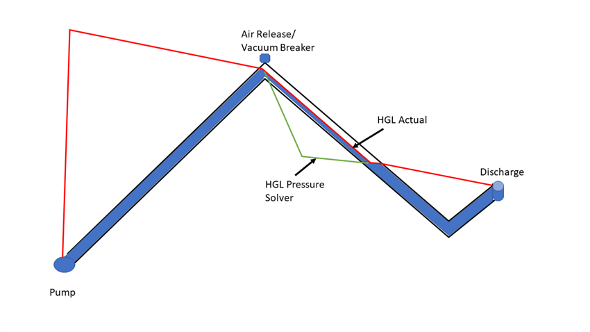
SewerCAD V8 XM (and later) provides an answer by incorporating a new air valve element. By placing an air valve at the high point, the pump sees the air valve elevation as its downstream boundary condition for instances in which pressure would have otherwise been negative at the high point.

For instances in which the force main functions as a pressure pipe for its entire length (e.g., during the high-flow condition), the pump correctly sees the force main outfall or downstream manhole as the boundary, similar to the behavior in older versions.
When the air valve is open, the hydraulic grade on the downstream side may be less than the pipe elevation. This can be displayed as the hydraulic grade line drawn below the pipe. This should be interpreted as a pressure pipe that is not flowing full. Full flow resumes at the point where the hydraulic grade line crosses back above the pipe. Details on the partially full pipe (between the air valve and where the pressure becomes positive) such as depth and percent full cannot be seen.

Because air valves have the possibility to switch status, they can lead to instability in the model especially if there are many air valves in the system. Symptoms of instability include:
1) Odd, unexpected results in the model such as hydraulic grade very low or very high where it should not be.
2) A message in the calculation summary stating that convergence was not achieved for a particular subnetwork
3) A "network unbalanced" message in both your User notifications and the pressure subnetwork details (in the Pressure Summary tab of the calculation summary)
To improve the stability of the model, it is desirable to force some of the valves closed. This can be done by setting the property "Treat air valve as junction" to True for those valves that are expected to be closed anyway. Basically because of the way that the air valve works behind the scenes, multiple air valves in series can be problematic, making it difficult for the numerical solver to converge on a balanced solution. Only the air valve nodes with the "treat as junction?" property set to "false" will act as air valve (pushing up the HGL as needed and simulating part full flow) when the situation warrants (HGL dropping down to the physical elevation). Therefore you only need to set this property to "false" for the locations that you actually need to use this feature. You can still keep other air valves in the model if you'd like (for display purposes or completeness for example) with the "treat as junction?" setting set to "true". Keeping too many air valves in the model, all set to "false" for "treat as junction?" will add unnecessary complication to the model, leading to potential convergence issues.
If all of the pumps upstream of an air valve are off, the pressure subnetwork is disconnected in that area and the model will issue warning messages for all nodes in that vicinity indicating that they are disconnected.
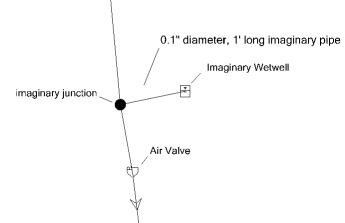
In addition, the profile between the air valve and the pumps that are Off will be inaccurate. To make the profile view accurate, you can place an imaginary wetwell on a short branch with a tiny diameter pipe at an Elevation (Initial) equal to the air valve elevation. This wetwell (which will not contribute significant flow) can eliminate the disconnected system message and correctly represent the fluid in the upstream pipe when the pump is off. Please note that the wetwell will need to be connected to the upstream side of the air valve. When the upstream pump is off, you may still see negative pressures downstream of the high point, which may be interpreted as part-full flow (the pipe may drain out).
For more information on troubleshooting air valves at high points, see the article in the "See Also" section below.
Implicit and Explicit Solver in SewerGEMS
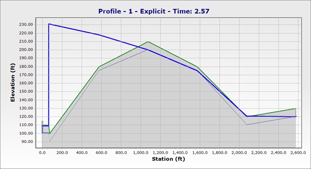
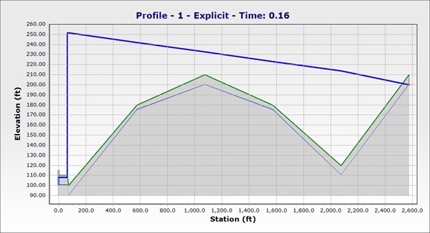
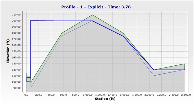
If you have access to SewerGEMS and can use the Implicit or Explicit (SWMM) dynamic solver, pumps will automatically recognize high points without the need for air valve nodes (you can still include the air valves without any adverse effect.) You will see part-full flow as expected in appropriate cases. Any attenuation effects from part-full flow (downhill from a high point such as the one shown below) are accounted for, but any additional headloss due to restriction from trapped air or gas from a non-functional air valve is not accounted for and would need to be estimated by adjusting the pipe diameter and/or friction coefficient.
Pump on, air valve open with part-full flow for a portion of the downhill pipe, pressure flow resuming further downstream:
Pump on, headloss gradient enough that the air valve remains closed:
Pump off, check valve at pump keeps uphill portion under pressure. Downhill portion takes time to drain out:
Note that large pressure sewer models may be harder to solve in the dynamic solvers, so you may need to use a smaller calculation timestep (implicit) or Routing Step (Explicit) to achieve stable results. See: Troubleshooting unstable SewerGEMS and CivilStorm results using the implicit solver
See Also
Troubleshooting Air Valves at High Points
AWWA Book: M51 Air Valves: Air Release, Air/Vacuum, and Combination, Second Edition