| |
Product(s): |
SewerGEMS, SewerCAD, WaterGEMS, WaterCAD |
|
| |
Version(s): |
V8i, CONNECT Edition |
|
| |
Area: |
Modeling |
|
Problem
How can I model individual components of a pump station such as an inlet well, Coarse Screen chamber, filter, bends and contractions?
Solution - Water
In WaterGEMS or WaterCAD, you can approximate the headloss through the pump station inner piping and components, using a few possible methods:
- Composite minor loss coefficient - Determine the composite minor loss coefficient (K) representing the losses through the whole pump station and assign it to the adjacent pipe. Be mindful of the diameter (and thus velocity) of that pipe, which has an impact on the minos loss equation (headloss=K*V^2/2g)
- Pressure Breaker Valve or General Purpose Valve - determine the specific total headloss through the pump station and use a PBV (constand headloss) or GPV (flow vs. headloss curve) to model it. See: Modeling a Constant Headloss
- Adjust the pump curve - determine the headloss through the pump station for a range of flow, and subtract those from the respective points on the pump curve. You would not be able to assess the correct pump efficiency if using this method.
- Neglect the headloss if you feel that it is relatively small
Solution - Sewer
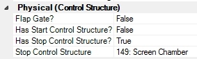
Usually the head losses through pump station facilities are so small that they can be neglected when you are running a model of the system. However, if you want to model them explicitly, you can treat the screen chamber as a control structure (see Start control structure in conduit properties) and you can treat the grit chamber as a conduit with a rectangular, trapezoidal or user defined conduit Section Type.
The wetwell itself would be modeled with the wetwell node element. The pump would connect downstream of the wetwell.
If the headloss through the component can be reasonably simulated with the standard orifice or weir equations, you can select "true" for "Has Start Control Structure?" or "Has Stop Control Structure" in the properties of the conduit, then define the properties of the control structure.
If you can model the component with the standard headloss equation in a pressure pipe, use the "Minor Loss Coefficient" field in the pressure pipe properties.
As a side note, one consideration when using control structures in the numerical solver. If the default Implicit dynamic wave solver has difficulty converging with these control structures in place and you cannot simplify them into a single structure (or neglect them), consider using the GVF Convex solver. (see Conduit Control Structure section of this article). There are other differences to consider (you can read about some of them in this article) but conduit control structure and pressure pipe minor losses tend to be more stable.
Here is another article with general information about modeling things that may not have an explicit element type:
How do I model devices, control structures, or other elements the software might not explicitly provide when modeling my system?
See Also
Setting up components of pump station in SewerGEMS (Forum Thread)