| |
Product(s): |
StormCAD, SewerGEMS, CivilStorm |
|
| |
Version(s): |
V8i, CONNECT Edition |
|
| |
Area: |
Modeling |
|
Problem
How can I model a ditch in StormCAD, SewerGEMS or CivilStorm?
Solution
Modeling a Ditch (or channel) as a Gutter to Capture Runoff
If the ditch is used as a gutter to convey runoff between catchbasins (inlets), it would be modeled as a gutter between the catchbasins elements that represent the inlets. You would use the Ditch inlet type by selecting Catalog Inlet as the Inlet Type in the catchbasin properties, then enter an inlet in the Inlet Catalog with the Inlet Type set to Ditch. For the Gutter Shape in the catchbasin properties, you would select Trapezoidal and enter the dimensions. In the attached gutter properties, you could either define that as trapezoidal as well, or select the option to set the gutter type as "same as start node".
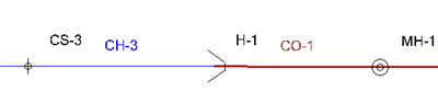
If the runoff enters on the upstream side of the ditch/channel, you cannot simply use a cross section element upstream of the gutter link element - it will need to start with a catchbasin node element. If you do not have an actual catchbasin there, you can configure it as a "fake" catchbasin with "percent capture" set as the inlet capture type, with a capture efficiency of 0% (or something very low like 0.001%) As seen in the below illustration. In this case however, it may be best to consider not explicitly modeling those upstream elements at all and rather have the catchment connect directly to the catchbasin element – the gutter geometry is built into the catchbasin element and when you see the calculated depth and spread at that catchbasin, it is based on the gutter geometry immediately upstream of the inlet opening (where they tend to be at their greatest, before some/all is captured). In other words, consider if there is value in modeling what happens in the channel between the immediate upstream side of the inlet and the point on the upstream of that gutter where the catchment flow enters.
Example model with both approaches (must use version 10.03.00.75 or greater):
Channel flow approaching Inlet example.zip

A note on V-shape gutter geometry vs. ditch/trapezoidal
Note that if your ditch has a V-shape, then you would still use the trapezoidal gutter shape at the catchbasin, because it represents the inlet location, where the cross section has a flat bottom due to the inlet grate itself. If you need to use a V-shape for the adjacent gutter link element(s), then you could use the trapezoidal shape with a very small "bottom width". See more here.
Modeling a Ditch to Convey Runoff
If the ditch conveys runoff captured by the storm drainage system (as opposed to a gutter with inlets), you can either use the conduit or the channel element.
With the Conduit element, it is modeled as a continuous prismatic section, in which case you would select Trapezoidal as the shape (either with the User Defined type or as a Catalog conduit). If the ditch changes direction or slope, model that as a transition node element between two conduits set as trapezoidal. The advantage of a conduit is that it can be sized with the constraint based design feature.
With the channel element, the cross sectional area of the ditch is modeled at the end nodes, set as Cross Section elements. So, if your ditch changes shape or slope over its length, you can model the different shapes and elevations at the cross section nodes at the start and stop ends of the channel. If you only have one cross section at the end and the other end is another node type such as a manhole, the program assumes the shape of the cross section over the length of the channel. See also: Are Channels prismatic or non-prismatic?
If your ditch discharges into a closed pipe, this can be modeled either as a headwall, manhole or transition node element. If the open channel flow goes through a headwall (culvert entrance) and then into the closed pipe, this can be modeled as channel -> headwall -> conduit, in order to account for the HDS-5 culvert entrance losses:
If your ditch transitions directly to the closed pipe with no headwall, this can be modeled as a manhole or transition node element. A manhole assumes a vertical vault and would account for structure losses based on the selected structure loss method (or no losses, if no structure loss method is set). A transition assumes a sealed junction (no vertical vault) but can also model structure losses. See also: Pressure Junction vs. Transition vs. Manhole
Shapes of Conduits
Conduit Shapes Word Document Download
See Also
Modeling a curb cut
Catchment outflow node to ditch
User notification, ""Ditch inlet type should be paired with a trapezoidal shaped gutter"