| |
Applies To |
|
|
| |
Product(s): |
WaterGEMS, WaterCAD, HAMMER |
|
| |
Version(s): |
V8i, CONNECT Edition |
|
| |
Original Author: |
Mark Pachlhofer and Scott Kampa, Bentley Technical Support Group |
|
Problem
When computing a model with parallel variable speed pumps (VSPs) or VSPBs, a red user notification appears (causing the run to fail) which refers to the pumps, or "Network Unbalanced" or "Cannot compute network hydraulics".
Background
Variable speed pumps have special rules because of the way they operate which make user notifications with them common.
Solution
The following rules apply to parallel VSPs. These are also outlined in the Help documentation included with WaterCAD, WaterGEMs, and HAMMER under the section titled "Parallel VSPs":
- Parallel VSPs must be controlled by the same target node.
- Parallel VSPs must be controlled by the same target head.
- Parallel VSPs must have the same maximum relative speed factors.
- Parallel VSPs must be identical, namely the same pump curve.
- Parallel VSPs must share common upstream and downstream junctions within 3 nodes (inclusive) of the pumps in order for them to be recognized as parallel VSPs.
- All upstream pipes should have the same diameter, roughness, length and minor loss coefficient, the same for all downstream pipes within the parallel VSP group. As opposed to the first five criteria a difference in these attribute values will not stop the calculation run. Only a warning user notification is generated for each attribute with at least one deviation. Note that the results within the suction and the discharge junction of the parallel VSP group will not be completely correct in this case.
Parallel VSPs need to be modeled with the same pump curve and the same control node. If this cannot be done in a model, there are two workarounds you can try:
a. Instead of modeling them as parallel VSPs, model one VSP at one station and then set the relative speed factor of other pumps by using logical controls.
b. Set the relative speed factor of all the pumps by using the logical controls.
Examples
This setup in a model may cause problems because the pumps are not all connected to the same upstream and downstream node. I this case you might get a "Network Unbalanced", "Cannot compute network hydraulics", or "Variable speed pumps not in parallel cannot be controlled by the same control node." user notification.
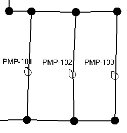
The setup for the VSPs that will compute looks like this:

Multiple VSPs discharging into the same pressure zone
When using VSPs or VSPBs, there should only be one such pump station discharging into a given pressure zone. If more than one set of VSPs are pumping into the same downstream network, they will end up "fighting" against each other and the hydraulics may not be able to solve. For example each one may be trying to maintain a different target pressure, and it may not be hydraulically possible for both pressures to exist at the given nodes at the same time, because of the interaction that occurs. Meaning, the flow and head from one pump station will impact the pressure at the target node for the other pump station.
If you do have a situation where this happens in the real system, you may need to determine how they actually operate in that real system and then mimic that in the model. For example it could be that there are manual controls, in which case you would model the pumps as fixed speed pumps, with logical controls that change the speed setting based on some condition. Care must be taken with this type of control, as a pressure-based condition can be very sensitive (the control action may have a large impact on the pressure, potentially causing the opposite control to immediately trigger).
See Also
How do I model parallel fixed head (target head) variable speed pumps that are controlled by flow in a downstream pipe?