| Product(s): |
WaterCAD, WaterGEMS, SewerGEMS, SewerCAD, StormCAD, PondPack, CivilStorm, HAMMER |
| Version(s): |
CONNECT Edition, V8i |
| Area: |
Modeling |
Overview
ModelBuilder is a tool available in Bentley OpenFlows products (at no extra cost) that allows you to create and update a model from a source file. A number of different source files are supported from any platform, such as shapefiles, CAD files, and Excel files. If you have an ArcGIS geodatabase file with modeling data, you can use these source file types if you are working in the ArcGIS platform. You can see a full list of supported data source formats in the Help documentation
The steps provided below will help you create a model and update an existing model with new data. The procedure example below uses shapefiles as the source of modeling information and WaterGEMS as the modeling software. However, the same general steps will work for most other supported source file types.
It is helpful to make sure that you have proper network connectivity for the elements in your source file. If the network is properly connected to start with, the network will be better connected in the water or storm/sewer product as well. If you are using a source file like a shapefile, ArcGIS geodatabase, or CAD file, when creating the model file you should make sure to turn on all of your snapping options, so the elements are actually connected in the source program and there aren't connectivity gaps. You should also make sure that you are laying out the elements in the correct order according to the WaterGEMS connectivity rules. This means that every pipe needs to have some type of node element attached at either end. Node elements include junctions, tanks, valves, reservoirs, and pumps.
ModelBuilder will allow you to create nodes at the end of pipes, so creating a node in the source file is not expressly required. However, it may allow for less clean up once the model data is created. For instance, all nodes created by ModelBuilder that are not already in the source file will come in as junctions. If the end node for a pipe is actually a pipe, you will need to manually change this in your hydraulic model. In addition, if elevation data is available for the nodes, you would be able to map the elevation data from the source file to the node. The water and storm/sewer products have tools that allow you to import elevation data or morph junctions into other element types.
Building a model with ModelBuilder (importing external data)
As mentioned previously, this example uses shapefiles as the source files to build the model. Given the nature for how the shapefiles were created, there are individual shapefiles for junctions, pipes and reservoirs. This procedure assumes that you have created a blank model in WaterGEMS menus, since we will building the model from the shapefiles.
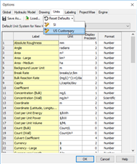
NOTE : Before importing the shapefile or any type of data through Modelbuilder, you should first set the required unit system SI or US customary through options (Tools>More>Options) and then import data through Modelbuilder to avoid spatial disconnection.
Importing a CAD file? (DXF file supported) See: Importing an AutoCAD or MicroStation CAD file using ModelBuilder
Open ModelBuilder
Once a new model is opened, you can open ModelBuilder. The ModelBuilder manager will be displayed. Click the New button to create a new ModelBuilder connection. Note: If you have used ModelBuilder to create models on your computer in the past, existing ModelBuilder connections will be listed in the ModelBuilder manager.

If you have an existing connection from a different computer that you want to use, you can click the Import/Export button to the left of the New button. This allows you to import an existing connection. If you import a connection, you would double-click the connection in the ModelBuilder manager to open it. Even though the steps below are likely already completed in the existing connection, this will allow you to make sure the data is correctly entered
Specify your Data Source
After creating a new file, the ModelBuilder Wizard will open. The first step is the "Specify your Data Source" section. First, select the Data Source type, and then choose "Browse" to select your source file, as shown
Note: As of Update 4 (version 10.04.00.106) .dgn, .idgndb, and .imodel are no longer supported file types. DGN files must now be exported to DXF format to be imported with ModelBuilder. IDGNDB and IMODEL files are currently no longer eligible to be imported using ModelBuilder. If you have questions, please contact Technical Support (Forum / Service Request).
Importing a CAD file? (DXF file supported) See: Importing an AutoCAD or MicroStation CAD file using ModelBuilder
Supported data sources for the Standalone, AutoCAD and MicroStation platform:
- Excel spreadsheets (XLS and XLSX)
- Access Database (MDB and ACCDB)
- CAD Files (DXF)
- ESRI Shapefiles (.SHP)
- OLEDB
- Oracle (12c)
- DBase
- HTML
Supported data sources for the ArcGIS Pro platform:
In addition to the data source types available in the Standalone version, the ArcGIS Pro platform also supports:
- ArcGIS Geodatabase Features
- Coverages
Supported data sources for the ArcMap platform:
In addition to the data source types available in the Standalone version, the ArcMap platform also supports:
- ArcGIS Geodatabase Features
- ArcGIS Geometric Network
- Coverages
For Esri Shapefiles, you can select more than one shapefile at a time by holding down the CTRL key on your keyboard and choosing multiple items.
For Excel spreadsheets, you will need to combine multiple files into a single file with multiple worksheets, which can then be selected in the next step below. Also, be sure that the Excel file is not set to read-only and that Excel is closed, for best results.

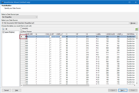
Once you have selected the files you want to browse, you do have some additional options that will allow you to filter the selection further. In the screenshot below you can see the three shapefiles that were selected for this example in the lower left. If you click the preview button, you will see information in the shapefile for the highlighted feature.
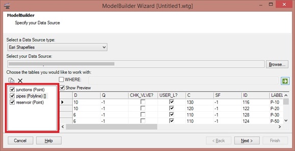
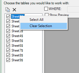
If you did not want to import one of the tables listed, you would simply need to uncheck the box next to it. If you have many tables/worksheets/layers and only need to select a small number of them, you can deselect all by right clicking in the list of tables and choose "Clear selection", then select the ones you want.
WHERE Clause
The WHERE statement in the middle of the dialog enables you to enter a SQL WHERE clause that will filter the data from the source so that only specific records will be imported. As an example, suppose you only wanted to import pipes with a diameter of 6 inches. You would check the box next to the WHERE statement and enter the appropriate clause. In this case, "D = 6". After clicking the compute button the source will filter so only the 6 inch pipes are listed.
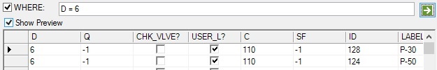
In this example, we want all pipes, so the WHERE clause is not used. Once you have reviewed your data, click Next. Note: The WHERE clause applies to one table. If you have a source file with more than one table (which is common for database source files), be sure to apply the WHERE query to each applicable table.
Note: If the field name has spaces, use brackets around it. For example: [internal diameter] = 16
Specify Spatial and Connectivity Options
The next screen lets you specify the units and connectivity options. This example uses feet as the coordinate unit. For metric models, the coordinate unit will likely be meters. You can choose the coordinate unit from the pull down menu at the top of the dialog.
Next, you will choose the connectivity options. The option "Create nodes if none found at pipe endpoint" will create a node at any pipe endpoint that doesn't have a connected node or is not within the specified tolerance of an existing node. To make this field active, click the check box next to it.
For the option "Establish connectivity using spatial data," this allows you to set a tolerance value for connectivity. If there is a node within the specified tolerance, pipes that are imported will be connected to that node. The unit associated with the tolerance is dictated by the coordinate unit you select.
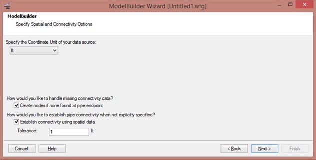
Note: It is generally good practice to check both of the connectivity options, as shown above. If there is no junction within the specified tolerance and if no node is created if none is found at the end point, the pipe will not be imported at all.
Once this is completed, click Next.
Specify Element Create/Remove/Update Options
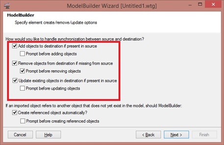
The next steps is to specify if data will be created, removed, and/or updated. When creating a model, the default settings (with Create and Update) selected is sufficient. More information on updating an existing model in ModelBuilder will be discussed in another section below.
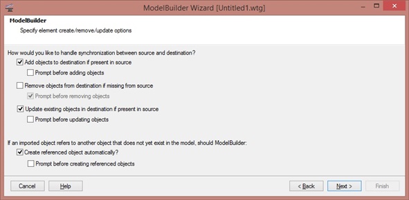
Add objects to destination if present in source (check box)
If this is checked, ModelBuilder will add the objects from your source to the model. Uncheck this if you just want to update attributes or geometry of existing elements and not add any new elements. By default it is checked to add data.
Remove objects from destination if missing from source (check box)
This option is useful when the source data is updated. ModelBuilder will delete elements in the model if the corresponding / matching elements are not found in the source data. For example, if you have some model with 1000 pipes which was created using GIS data containing 1000 pipes. However, now the GIS data was updated and has only 200 pipes. When you check this option, ModelBuilder will delete the rest of the 800 elements and the updated data of 200 will only be available.
Update existing objects in destination if present in source (check box)
If this option is checked, ModelBuilder will only update the elements already present in the model (mapped attributes and geometry/location/vertices). It wont add or remove elements. In the above example, in the original 1000 pipe data suppose you only had the length of the pipes in the attribute data, but in the 200 pipe data you have all the related data such as material, Hazen William's C etc. and updated length and alignment (geometry). This can be useful if the source data is regularly updated and those changes need to be reflected in the existing hydraulic model elements.
Click Next once the right options are selected.
Specify Additional Options
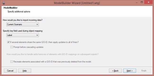
This section allows you to choose where the imported data will go and what key field will be used in the field mapping. Typically, the incoming data will go to the current scenario, so the default setting in the first pulldown menu will be sufficient.
The key field is important in that will be a unique identifier used so that ModelBuilder knows which element the data in the source file will be assigned to. The options are either Label or GIS-ID. This example will use the Label selection. GIS-IDs can be imported if you want to keep data in your GIS in sync with the hydraulic model you are creating in ModelBuilder. For more information on GIS-IDs, please refer to the product Help documentation or this link.
Starting in CONNECT Edition Update 1, a new spatial join feature is included in this step. This allows you to bypass the key field for select cases to add or update based on the closest matching geometries. Typically, the key field is the best way to add or update elements with ModelBuilder, but spatial joins can be useful cases like populating an existing model with GIS-IDs.
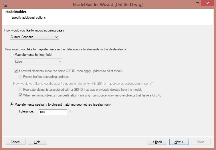
The tolerance has a default of 100, with the unit based on what was selected for the connection. After clicking Next to go to the Field Mapping section of ModelBuilder, you will see that the key field is set to the <label> field generated by ModelBuilder. If you want to use a label from the source file as the label in the model, you can use the field mapping in the lower left to set the label, as well as any other properties of note.
Elements in the data source that don't match with any existing elements in the model will be created in the same way that an element with a key field not already in the model would be created.
When synchronizing into the model with spatial join enabled, ModelBuilder will first look for exact matches spatially and map them. Then searches are done on the remaining elements using the specified tolerance. If there are multiple nodes found within the tolerance, the closest one is chosen. If there are multiple polylines found, the distances between the start, mid, and end points are used to choose a match. If there are multiple polygons found, the distances between centroids are used.
Click Next.
Specify Field mappings for each Table/Feature Class
In this step, the data source tables are mapped to the desired modeling element types, and data source fields are mapped to the desired model input properties. The tables are listed on the left side of the dialog. In this example, we see tables for junctions, pipes, and reservoirs. Each of these three will need to have data mapped in order to proceed to the next step. If for some reason, you do not want to map one of this, you will need to click the Back button until you are in the first step of the ModelBuilder Wizard and uncheck the table.
First, we will set up the field mapping for the junctions. With this highlighted, the Table Type pulldown menu will only show node elements. We will select the appropriate options, in this case "Junction". Next, the Key Field needs to be selected. This needs to be a unique identifier in the dataset. If you are unsure which of the available fields is unique, you can click the Preview tab to view the data. In this case, the shapefile contains a field called "LABEL" that can be used. Note: If the chosen Key Field is not unique, not all elements will be imported. Instead, one instance of a given element will be created, and any subsequent reappearance of the key field identifier will only update the existing element.
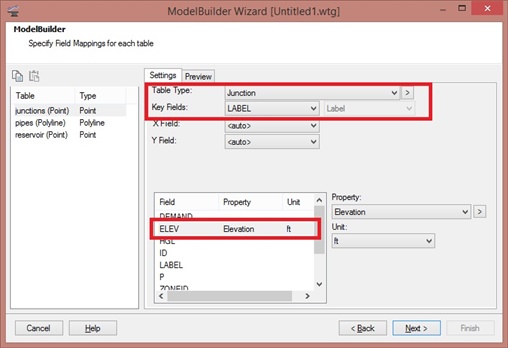
After selecting the Table Type and Key Field, you will then want to map any relevant data from the source file to the hydraulic model. What you will include will depend on the data you have available. In this example, the elevation data is present. Given that, highlight the field in the table (ELEV, in this case). Next, go to the Property pulldown menu and choose the appropriate property ("Elevation"). If needed, adjust the unit as well. Do this for any field in the source file that you want included in the hydraulic model.
Note: for enumerated fields (section size, initial status, etc), the values in the data source must exactly match (case sensitive) the available options in the model. See: "Unable to assign attribute ... for element because enumeration value ... is not valid."
Once this is complete, highlight the next table from the list on the left and complete the same steps. For the pipe table, the Table Type "Pipe" is chosen and the Key Field is "Label." Data like pipe diameter and user-defined length is mapped from the source file to the hydraulic model.
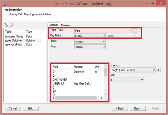
Note: Entries for the X and Y coordinates (for node elements) or Start and Stop nodes (for pipes) may not be required for all element types. Shapefiles, CAD files, DGN files, and most ArcGIS files include spatial data that allows for the spatial location of the elements to already be included. If the source file is an Excel spreadsheet, X and Y coordinates and Start and Stop nodes will need to be specified.
Once all of the field data for the tables have been mapped, click Next.
Specify Snapshot Settings
Starting the CONNECT Edition Update 1 release of the OpenFlows / Hydraulics and Hydrology software, you can now use the new Snapshots feature in ModelBuilder to keep track of what has changed in the GIS since they were last imported into a model, and to only bring in those changes when performing a sync-in. The goal of this enhancement was to allow you to preview the changes since the selected snapshot that would be brought into the model.
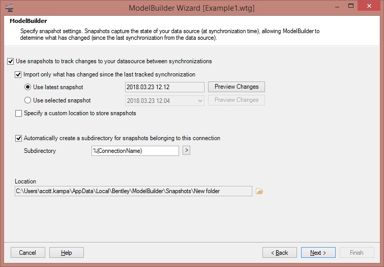
If you check the box for "Use snapshots to track changes to your datasource between synchronizations, you will be able to create snapshots to that you can see what has changed since the last input. If this is the first snapshot you are creating, the item for "Use latest snapshot will be blank. But once the snapshot is created, you will be able to preview the changes for the latest snapshot for from any other snapshot that is available. The snapshot is automatically saved to a folder in your user profile and is denoted the date and time the snapshot was created.
Using the preview changes button on the snapshots page of the ModelBuilder wizard, you can preview the differences before performing the synchronization into the model. If a valid snapshot is selected, either through the get latest or selected option, the appropriate preview changes button will be clickable. This will look similar to the screenshot below:
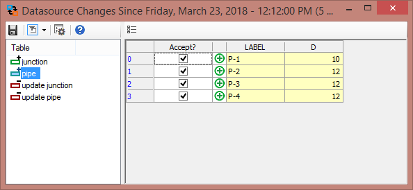
The Preview Changes option lets you review what elements may be added, removed, or updated after completing the ModelBuilder run. The following link has more information on this feature: Using ModelBuilder snapshots to help track changes and updates between source file and model file.
Create Model Now?
In the next step, you will choose to create the model. You can also specify selection sets that will include new or updated data. In this case, the defaults are selected.
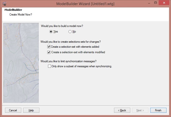
Click Finish.
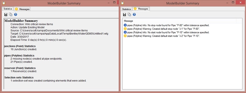
ModelBuilder Summary
After the import is completed, a summary window will appear, detailed the number of elements created, updated or removed. In this case, 16 junctions, 21 pipes, and one reservoir were created. In addition, note that two additional junctions were created at the end nodes of pipes. This is because the there were points in the model where no end node was found within the tolerance set in ModelBuilder. By clicking the Messages tab. we can see details of this.
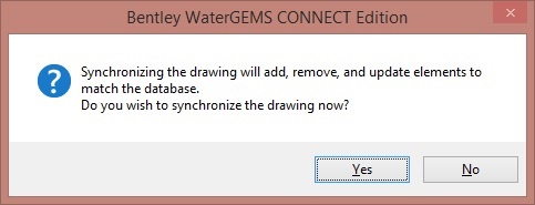
After review the summary, close it. Then close the ModelBuilder manager. You will be prompted about synchronizing the drawing. Click Yes.
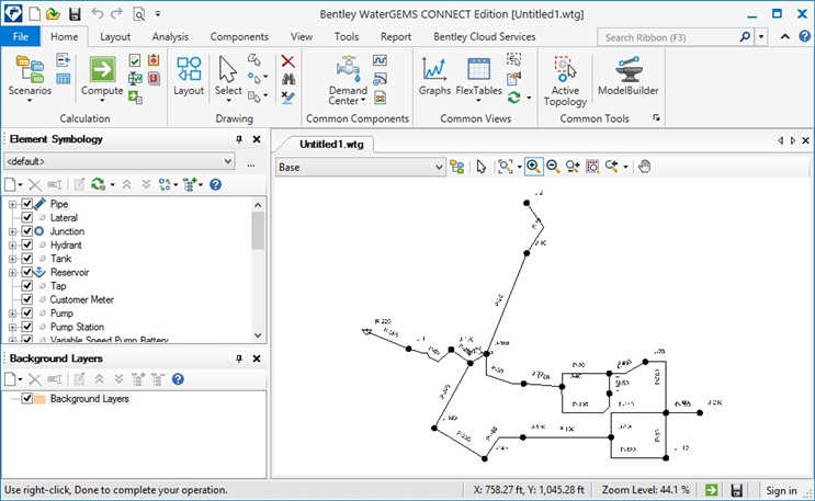
The data from the source file will now be imported into the water or storm/sewer product, as shown below.
Updating an existing model using ModelBuilder
Source file data is frequently updated as more is learned about the system, new facilities are constructed, or old facilities are abandoned. Because of this, it is often necessary to update an existing hydraulic model with new information from the source file as it becomes available. ModelBuilder provides the means to do this.
The process for updating an existing model with ModelBuilder is similar to creating one. The key difference is the settings in the "Specify element create/remove/update options" section of the ModelBuilder wizard. Depending on how the data was changed in the source file, you may want to check all of the options to create new elements in the existing model (if new elements were added), remove items from the hydraulic model (if they no longer existing in the source data), and update elements (if the data for an existing element has changed).
In this example, the source file for the model shown above has been changed based on a review of the system. The diameter of one of the pipes has been changed, another pipe and a junction were removed, and some addition pipes were added to the system.
To start updating the model, open ModelBuilder. Since this model was already built, there is an existing connection in the ModelBuilder manager, as shown in the screenshot below. Because of this, all that you might need to do is click the "Build Model" button shown in red.
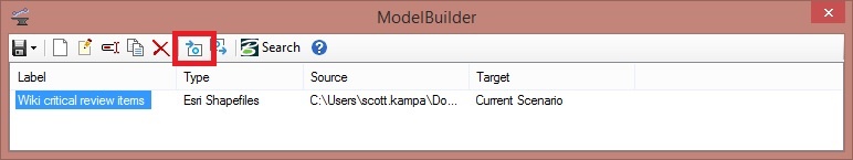
This would update the model with new information, including creating any new elements that might not exist currently. However, recall that the "Remove" option in the "Specify element create/remove/update options" was not checked when we created the model initially. For that reason, it will be good to review the settings in the model and make the appropriate adjustments. To do this, double-click the existing connection.
The first two steps ("Specify your Data Source" and "Specify Spatial and Connectivity Options") will follow the same steps as found in the relevant sections above. In the next step--"Specify element create/remove/update options"--you will want to make sure the options to create, remove, and update elements are all checked. This will assure that new elements will be created if they are in the source file, elements that are not in the source file are removed from the model, and that existing elements are updated if there is new data present.
Click Next.
The "Specify Additional Options" and "Specify Field Mapping" sections will be the same as the section above. If you are using an existing ModelBuilder connection, you will likely not make any changes to these, unless there are additional data that you want to map from the source file to the hydraulic model. The "Specify Snapshots" allows you to preview changes made to a model to allow for better tracking and management of updates to the GIS. See the section on snaps above or this link for details.
In the "Create Model Now?" section, select "Yes" and click "Finish." The ModelBuilder summary will appear. Close the summary after reviewing it, and close the ModelBuilder manager. After synchronizing, the updated model will appear, as shown below.
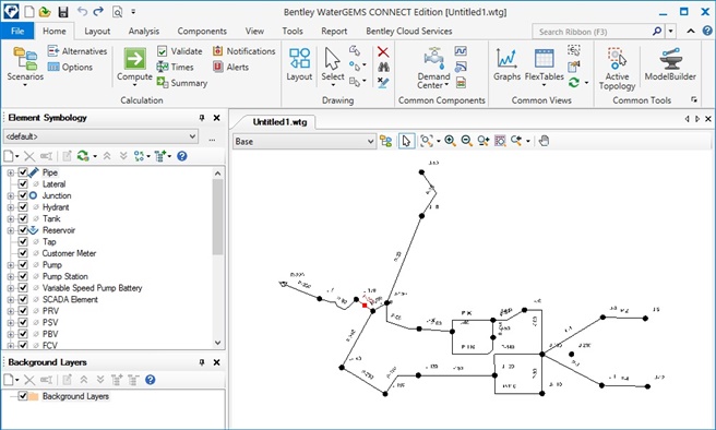
The pipe highlighted in red on the left side of the drawing had an updated pipe diameter in the source file. The pipe diameter in the model now reflects this new information. In addition, four new pipes are added to the model on the right side of the drawing, replacing a pipe that was deleted from the source file.
Notice that there is a junction that was not removed from the drawing. This occurs because the junction shapefile used in the original creation of the model was not changed to remove it, even though the pipe shapefile was updated to remove the pipe. This shows that there may need to be some cleanup required in a model after using ModelBuilder. In this case, simply deleting the junction will remove it from the hydraulic model. However, you may want to review the source file to make sure that the changes are reflected there as well. Another option would be to use the Sync Out function in ModelBuilder. This is used to change the source file to reflect changes made in the hydraulic model. The following link has additional details on using this feature: Using the Sync Out function to update source files using ModelBuilder
Can we copy data from Preview tab in ModelBuilder?
You can copy the data values from Preview tab, however the column labels /headers will not be copied.
1) Click the row header area to select the first row (see screen capture).
2) Hold down [Ctrl] + [Shift] and press the [Down Arrow] key (to select the remaining rows).
3) Press [Ctrl] + [C] to copy the selected rows to the clipboard.
Note : When you click at the column header, the data will be sorted by that column, so you will observe some changes taking place in data.
See Also
Introducing individual Property Connections to your model
Updating the Sync Out function to update source files using ModelBuilder
Setting Boolean (True/False) Fields using ModelBuilder
Import a CAD (eg. DXF or DGN) flle using ModelBuilder
Unable to set zone back to "<None>" using ModelBuilder
Hydraulics and Hydrology Forum
Troubleshooting making a SCADA connection to Oracle database