| Product(s): |
HAMMER |
| Version(s): |
CONNECT Edition, V8i |
| Area: |
Modeling |
| Original Author: |
Jesse Dringoli, Bentley Technical Support Group |
Overview
This TechNote explains how the surge valve element works and its typical application in HAMMER. It also provides an example model file for demonstration purposes.
How it Works
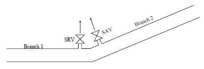
The Surge Valve element encompasses both a Surge Anticipator Valve (SAV) and Surge Relief Valve (SRV). You can configure the valve to act as one of these types or both.

The main purpose of the surge valve is to alleviate high pressure transients (upsurges) that can occur in some situations. This is done by opening the surge valve at key times during the transient simulation.
Important Note: when this valve opens (both the SRV and SAV), it discharges to the atmosphere, not into/between a connected pipe element (see more here). Also, if sub-atmospheric pressure occurs at the surge valve location, air inflow is not modeled. If sub-atmospheric pressure is simulated, it is likely that other surge protection approaches should be considered.
Usage - Surge Anticipator Valve
In a typical operation, when the pressure at the SAV valve falls below the threshold value, it opens up to the atmosphere in anticipation of a subsequent upsurge of high pressure. An upsurge like this is typical of an emergency pump shut down, so the valve is usually installed at the discharge header. The surge anticipator valve is already open when the high pressure transient reaches the valve; sensing of high pressure is not required to initiate the opening of the valve. The valve then closes slowly so as not to cause a transient.
In some cases, these valves can be a cheap protection alternative to a surge tank or hydropneumatic tank, but are typically not as effective. This type of valve is more effective than a SRV when high-pressure transients occur so quickly that the SRV does not have adequate time to respond and open. Care must be taken in setting the low pressure activation point to avoid premature opening before the pump has spun down, since that can cause a very steep negative transient wave.
In addition to opening and closing based on a threshold pressure, you can operate the SAV based on time. In this case, you would define not only the time to open and close, but also how long the SAV will stay open.

Note: The SAV is treated as a junction with no demand during the initial conditions calculation. In addition. air inflow is not supported if the pressure drops below zero during the transient simulation.
Attributes - Surge Anticipator Valve
Threshold Pressure (SAV) - This is the pressure below which the valve opens up to the atmosphere.
Discharge Coefficient (when SAV Fully Open) - This is located under the "Transient (Physical)" section of the properties and is used to define the discharge coefficient (Cv) of the SAV when it is fully open. Basically at the time when the valve is fully open, the discharge out to the atmosphere is represented by this coefficient. For more information on what HAMMER expects for this discharge coefficient, see: What is the "Discharge Coefficient"? For further guidance, see: How can I calculate the discharge coefficient (Cv) of a SAV?
Diameter - This is not used in the HAMMER calculations but useful for display purposes. Flow through the valve is determined based on the discharge coefficient when fully open and valve type. It is assumed that the percent of open-area curve for each valve type corresponds to its discharge coefficient curve.
SAV Closure Trigger - This identifies the method used to trigger closure of the SAV after it has opened. It can either be based on time or a threshold pressure. When time based, you must enter a specific duration that the valve is open. When pressure threshold based, the SAV will begin to close when the pressure at the SAV rises back above the threshold pressure.
Depending on the setting for SAV Closure Trigger property, additional properties will be displayed.
When using Threshold Pressure as the closure trigger:
Time for SAV to open - Once the pressure falls below the threshold pressure, this is the time it takes for the SAV to become fully open. If the pressure rises back above the threshold before this time has elapsed, the valve will begin to close. If it does not rise above the threshold until after this time has elapsed, the SAV will remain fully open until that time.
Time for SAV to close - This is the time it takes for the valve to close, beginning when the pressure rises above the threshold pressure.
When using Time for the SAV Closure Trigger, the same properties above are available, as well as:
Time SAV Stays Open - The time that the SAV stays fully open between the end of the opening phase and the start of the closing phase.
Usage - Surge Relief Valve
The SRV opens up to the atmosphere when the pressure at the SRV rises above the threshold pressure and closes immediately after pressure drops below this setting. This valve is usually installed across the pumps and discharge headers or at critical points along the pipeline in order to control the maximum system pressure. If the SRV closes too quickly, severe transients could occur. The SRV may be too slow to open after a power failure (fast, sharp transient pulse), so it is better for protection against gradual over-pressurization and to limit the pressure rise during normal pumping operations. In some cases, these valves can be a cheap protection alternative to a surge tank or hydropneumatic tank, but may not be as effective.
In a typical application, the SRV is comprised of a vertical-lift plate which is resisted by a compressed spring. At the threshold pressure, there is an equilibrium between the compressive force exerted by the valve's spring on the movable plate and the counter force applied by the pressure of the liquid. To see how the SRV outflow is calculated based on the system pressure, SRV diameter, threshold pressure and spring constant, please see the attached spreadsheet (NOTE: you will need to be logged in first or the link will not work)
Starting with HAMMER CONNECT Edition Update 3 (build 10.03.03.72), you can also define how the SRV opens and closes based on time. In such a case, you would enter the time for the SRV to open and the time to close. Note: Time-based operation does not support interruption in the opening and closing of the surge valve.
If you wish to have more control over the outflow characteristics of your surge relief valve (for example for a pilot operated valve instead of one that uses a spring), an alternative method would be to use a TCV (throttle control valve) with a short, large diameter pipe downstream of it connected to a discharge to atmosphere element (configured based on the characteristics of the opening to the atmosphere). The TCV element has many options for modeling its closure characteristics so you could potentially use discharge coefficients and a user defined valve characteristics curve to model the characteristics of your surge valve's opening (relating pressure to outflow). You would need to use trial and error to determine the operating rule pattern for the TCV, to control when it opens/closes and how quickly. See more here: Modeling Reference - Valve Closure.
Calculation Assumption Notes:
- Orientation/connectivity: The SRV is assumed to discharge to the atmosphere, not between pipes. (see link further below)
- Initial conditions: The SRV is treated as a junction with no demand during the initial conditions, simulating an SRV in the closed position.
- Negative pressure and air/vapor: Improvements were made to SRV calculations starting with version 10.03.03.72 (and higher). In the newer version, regardless of whether the SRV is connected to one or two pipes, the pressure is able to drop down to the vapor pressure limit (default: -14 psi) but vapor volume is not tracked. In older versions, negative pressure was only possible with SRVs connected to a single pipe (at a tee / dead-end), while the pressure at SRVs connected to two pipes was limited to zero.

Attributes - Surge Relief Valve
Threshold Pressure (SRV) - The pressure above which the SRV opens up to the atmosphere. This may be controlled by a spring, piloting, or other mechanism.
SRV Type - Select between Spring Loaded and Time-Based.
Diameter (SRV) - The diameter of the opening available to release fluid from the system. It correspond to the "area" of the plate shown in the above diagram.
Additional properties are available depending on the SRV Type you select.
If you use the Spring Loaded option:
Spring Constant - Change in restoring force of the return spring per unit lift off the valve seat. A possible value is 150lb/in. For a linear spring, the lift, x, is given by the equation: A (P - P0) = k x, where A is the pipe area, P is the instantaneous pressure, P0 is the threshold pressure, and k is the spring constant. In this formulation, the acceleration of the spring and plate system is ignored. As the plate lifts away from the pipe due to the excess pressure, more flow can be discharged to the atmosphere. Currently there is no maximum imposed on how far the plate can lift.
If you use the Time-Based option:
Time for SAV to open - The time it takes for the SRV to become fully open.
Time for SAV to close - The time it takes for the SRV to close.
Usage - Combined Surge Anticipator and Surge Relief Valve
If you set the surge valve property field SAV/SRV Type, to "Surge Anticipator & Relief Valve," the surge valve will operate as both a surge anticipator valve and a surge relief valve. The properties for both types will be available and in the thresholds for surge valve type occur, the surge valve will operate as that type of the valve. See the sections above for information on how surge anticipator valves and surge relief valves operate.
Note: An issue related to the combined surge anticipator and surge relief valve, where a valve set as the combined SAV/SRV does not operate correctly for the SAV portion of it. This issue was resolved with a patch for HAMMER version 10.04.00.108. This issue is also resolved in later versions of HAMMER. New versions are available through the Software Downloads page. For the patch, please contact technical support.
Reporting
After computing the transient simulation, you will see a user notification (Analysis > User Notifications) indicating the volume of water that discharged out of your surge valve. For example:
"The total discharge through surge anticipator valve and/or surge relief valve = 2.619 m³."
If your surge valve is at a "Tee" (separate short pipe going from the main line to the surge valve at a dead end) then you can graph the flow over time by adding the pipe end as a report point. To do this, go to Analysis > Calculation Options, open your transient calculation options and make sure "report points" is set to "all points", or "selected points", with the surge valve added as a report point in the report point collection. Then, after computing the transient simulation, go to Analysis > Transient Results Viewer and plot a time history of "flow" for the pipe endpoint adjacent to the surge valve.
If your surge valve is not at a "Tee" and is instead in-line / in-series with the main pipeline (two adjacent pipes), you will not be able to directly report the discharge hydrograph (in the current version of HAMMER.) You would need to plot a time history of flow for the adjacent upstream and downstream pipe endpoints and find the difference.
Example Model
A sample model can be found in the installation folder found at C:\Program Files (x86)\Bentley\HAMMER\Samples. The surge valve sample file is called "Surge_Valve_Example.wtg." Some older versions of HAMMER V8i will not include this file. If it isn't there, you can download a sample file here:
Click to Download
Note: You will need to be signed in or the link above will not work.
The sample model is for example purposes only. The sample file from the download link can be opened in HAMMER V8i version 08.11.00.30. You can find additional information under File > Project Properties.
Modeling a Surge Valve that opens between pipes
See: Modeling a Surge valve that opens between two pipes or that is controlled by pressure at a different location
Reference
- HAMMER V8i, Transient Analysis and Design training course manual (TRN013190-1/0001)
See Also
Product TechNotes and FAQs
OpenFlows Product Tech Notes And FAQs
Protective Equipment FAQ
General HAMMER V8i FAQ