| Product(s): |
CivilStorm, SewerGEMS |
| Version(s): |
10.00.xx.xx, 08.11.xx.xx |
| Area: |
Modeling |
Background
In some situations, multiple in-sag inlets may experience flooding and water will pond above them (for example a parking lot). How can this be modeled so as to have one common flooded area above multiple inlets? (multiple inlets sharing one surface storage)
Surface Storage Approach
The "Surface Storage" option in the catchbasin node element provides a way to store water above the rim elevation of the inlet. When using the surface storage option, when the HGL at the node rises above the rim elevation, flow will start to "spill" into the surface storage and the HGL will be allowed to rise further.
However, the surface storage modeled with this option is kept separate for each inlet. Meaning, overflow for a particular inlet will only be stored in its respective surface storage and must drain back down into the respective node. If a gutter is attached, water will only pass down the gutter when the HGL reaches the maximum surface ponding elevation.
So, if you have multiple catchbasins that experience flooding at the same time and essentially create a single pond above them, and you would like to model this so that each inlet "senses" this single storage of water and handles it accordingly, you may need to use a Pond.
Pond Approach
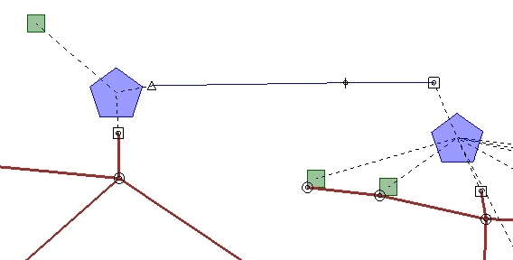
With a pond approach, you would replace the inlets with pond outlet nodes, connected to a single pond. The pond elevation-area or elevation-volume curve would be set up to represent the in-sag area above the inlets that water would pond up in. Overflow from the catchbasin inlets would enter the pond and the change in storage and elevation would be communicated to each of the inlets. When the conditions warrant, water stored in the pond would recede back into the sub-surface network.
The pond outlet node's "has control structure" property would be set to "true" and a Riser could be considered as the composite outlet structure. A riser simulates weir flow at low depths and orifice flow at submerged depths, similar to typical grate and curb inlets.
In many cases you will have multiple sub-surface pipes (conduits) connected to the catchbasin. Since multiple conduits cannot connect directly to a pond outlet node, a large diameter, short length pipe is suggested, between the catchbasin location and the pond outlet. The catchbasin in the model would be replaced with a manhole with a bolted cover ("Bolted Cover?" = True). With this setup, the hydraulic grade should be appropriately "communicated" between the pond and the pipe, though this could pose a hydraulically challenging situation, potentially requiring some calculation option changes. (see further below)
The invert of the end of the conduit next to the pond outlet would be set equal to the invert of the sub-surface pipe leaving the catchbasin vault. The invert of the Riser outlet component and the bottom elevation of the pond would be set equal to the inlet elevation.
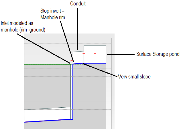
Another approach would be to connect the short conduit between the pond bottom and the inlet (manhole) rim elevation. Meaning, set the conduit stop invert equal to the manhole rim. This will enable the numerical solver to "see" this conduit essentially as a gutter between the inlet surface and the pond. The pond outlet structure orifice or riser crest elevation would be set equal to the pond bottom. See below screenshot of the profile view:
Example Model
Here is an example model demonstrating the pond approach above, including upstream gutters attached directly to the pond via outfalls. Note that this model cannot be opened in versions of SewerGEMS or CivilStorm below 10.01.XX.XX.
Ponding above multiple inlets.zip
A Note on Stability
Note that the pond approach may be very hydraulically challenging for the numerical solver and may yield unstable results and/or high continuity error (as seen in the calculation summary). It is recommended that you try the Explicit (SWMM) solver (change this in the calculation options) with a small Routing Time Step for best results. (as low as 0.5 or even 0.1 seconds in extreme cases) If this does not help, consider approximating with individual surface storage in the properties of each catchbasin. In most cases, water may pond up at the same time for each of the inlets in question, so this may be an acceptable workaround and should be more stable.
See Also
Interpreting results when using manhole or catchbasin Surface Storage
Troubleshooting unstable SewerGEMS and CivilStorm results using the implicit solver