| |
Product(s): |
WaterGEMS, WaterCAD |
|
| |
Version(s): |
V8i, CONNECT Edition |
|
| |
Area: |
Modeling |
|
|
Authors: |
Tom Walski, Jesse Dringoli |
|
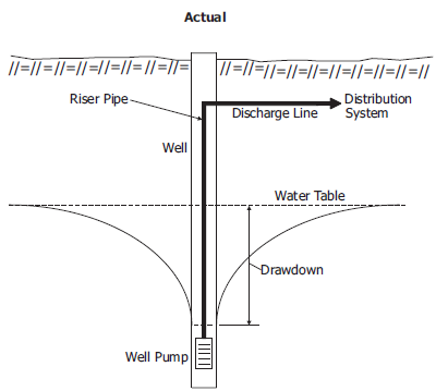
Problem
How can I account for drawdown effects of a well pump, for either a fixed speed or variable speed pump?
Solution for Constant Speed Pumps
For a constant speed pump, well drawdown is normally accounted for by offseting the pump curve by the difference between the static and pumped groundwater elevations. The drawdown amount would be subtracted from the pump head values, and the new values would be used for the pump curve head data.
See more in the help topic "Modeling a Pumped Groundwater Well" and the Advanced Water Distribution Modeling and Management book chapter 8.3

Solution for Variable Speed Pumps
With a variable speed pump, the above approach does not work out as well, because of the way the speed scales the pump curve. In this case, a GPV headloss curve is needed, next to the pump. Below is an explanation.
In the below spreadsheet file there are two sheets.
Well-VSP-Drawdown.xlsx
The first shows the way you can account for drawdown by modifying the pump curve. This generally works well for a constant speed pump. However it becomes quite difficult for a VSP because the speed is not known before the calculation.

What really happens is that the drawdown can be approximated by reducing the suction head as a function of flow. This solution looks like the graph below and is on the second sheet in the file. The blue system head curve is no drawdown while the orange accounts for drawdown.

Note that the results for flow are the same for both sheets. For example at N (speed) = 0.8, Q = 70. However, the pump heads are off for the pump curve adjustment approach because the pump head curve was adjusted. This implies that it is better to adjust the system head curve than the pump head curve. But the program can’t do that directly without iterating. So, we need to insert something to cause head loss as a function of flow. This can be done with a General Purpose Valve (GPV) that gives the same head loss as the pump drawdown rate (0.2 ft/gpm).
Consider the below WaterCAD/WaterGEMS model which contains a VSP and GPV.
VSP Drawdown Example.zip
NOTE: this model is saved in the CONNECT Edition (10.00.00.49) and cannot be opened in earlier versions.
The pipes in this model were calibrated to provide the same head loss vs. flow curve. The model was computed for three speeds with drawdown and once without drawdown (4 scenarios). As you can see, the model results match the spreadsheet. Note that the GPV in this model was placed on the discharge side, but using the suction side may be more accurate and would allow you to look at NPSH, though the pump operating points are the same.
In conclusion, the best way to model drawdown in a well (even for variable speed pumping) is to approximate the drawdown rate (e.g. 0.2 ft/gpm) with a GPV that has a curve with the points that correspond to the drawdown (e.g. (0,0) and (100,200)).
See Also
Modeling a submersible pump
Modeling a Pumped Groundwater Well (Help topic)