| |
Applies To |
|
|
| |
Product(s): |
HAMMER, WaterGEMS, WaterCAD |
|
| |
Version(s): |
V8i, CONNECT Edition |
|
| |
Area: |
Modeling |
|
| |
Original Author: |
Jesse Dringoli, Bentley Technical Support Group |
|
Overview
This technote explains how various types of valves work and their typical application in HAMMER and in WaterGEM / WaterCAD. It also provides an example model file for demonstration purposes. A video demonstration is found at the bottom.
Primary Valve Elements
The main "valves" icon on the layout toolbar offers several generic valves: GPV, TCV, FCV, PRV, PSV and PBV. These are sometimes collectively referred to as "valves of various types" in older versions of HAMMER.


These valve elements serve various purposes and are frequently used in steady state or Extended Period hydraulic models. They can generally be categorized as flow control. For example, the GPV defines a curve of flow versus headloss, the FCV (Flow Control Valve) controls flow to a set point and the PRV (Pressure Reducing Valve) controls the downstream pressure to be below a set point.
Which valve element should I use?
For general valve closure purposes such as gate valves, isolation valves, etc, it is recommended that you use the TCV valve type (throttle control valve). This valve represents a standard headloss or discharge coefficient during the initial conditions. So, in the below example of an initially open valve, you would specify the loss coefficient representing the losses through the fully open valve.
If you have a valve that actually throttles to control the flow or pressure, you would use the FCV, PSV or PRV element. Keep in mind that when these valves are active (throttling to maintain their setpoint), the initial position will be calculated by the initial conditions solver and you will see a calculated percent open in the Results section of the properties. If you need then then close the valve during the transient simulation, you will need to be aware of this initial position and match it up with the starting relative closure of your transient Operating Rule (closure pattern).
Dynamic Valves (FCV, PSV, PRV)
The important thing to understand about dynamic valves like FCVs, PSVs and PRVs is that their controlling effects (pressure reduction, flow control, etc) only apply to the initial conditions calculation (steady state or EPS). For a given steady state or EPS timestep, a specific headloss occurs across the valve. For example, in order for the PSV element to sustain upstream pressure, a specific headloss occurs through the valve, such that in order to balance energy across the network, the upstream hydraulic grade ends up being higher than the PSV set point. During the transient simulation, a discharge coefficient is calculated based on that valve's headloss during the initial conditions timestep.
Note: the following equation is used to convert between headloss coefficient and discharge coefficient: H = 39.693 * D^4/Cv^2 Where: D = Diameter (ft), H = Headloss coefficient (K), Cv = discharge coefficient (cfs/ftH20^0.5) It can be re-written as: Cv = ((39.693 * D^4) / H)^0.5 See more: What is the "Discharge Coefficient"?
As the transient simulation progresses and the system conditions change, these valves will not automatically react, like they do during the initial conditions. Meaning, if the transient conditions cause a higher flow through a FCV, it will not automatically throttle (change its headloss) to react accordingly. The reason is because HAMMER assumes that these valves cannot react fast enough during the transient simulation. So, they will stay in a fixed position based on the aforementioned discharge coefficient from the initial conditions.
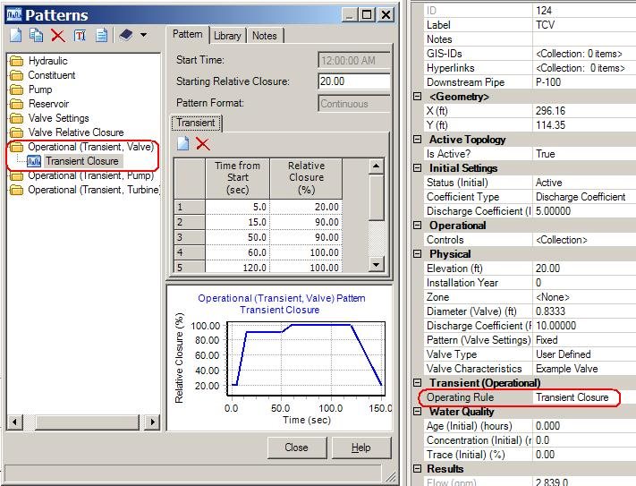
However, the user can manually open and close these valves during the transient simulation by using the Operating Rule. The operating rule is an attribute of the valve, found under the "Transient (Operational)" section of the properties. It allows you to define a pattern of Time versus Relative closure, to be using during the transient simulation. "Relative closure" means the percent closed, so 100% means fully closed and 0% means fully open. See below image.
Note: An exception to this is that PRVs, PSVs, and FCVs can be modeled as modulating valves, which will throttle automatically to meet a setpoint during the transient simulation. See this related article: Using Modulating PRV, PSV, and FCV in a transient simulation.
Throttling Control Valves (TCV)
The TCV element can be used to model a valve that starts in a specific position and follows a custom closure pattern. It also enables you to have full control over the closure characteristics as you can define the coefficient type as a discharge coefficient, minor loss coefficient or valve characteristics curve. See further below for more details on valve characteristics curve, and the following article for more general details on the initial conditions calculations and the use of the different coefficient types: How headloss is calculated based on the different Status (Initial) settings for a TCV
For example, if you have a gate valve that is fully open in the initial conditions and you want it to fully close during the transient simulation, you could define your operating rule with a starting relative closure of 0% (fully open) and pattern that rises to 100% (fully closed) at some point. You would then select that in the valve's properties, under the "Operating Rule" field. You can analyze the effect of various closure patterns either by manually changing the operating rule and re-running the simulation or by creating multiple scenarios, computing a batch run in the scenario manager and then individually examining the transient results.
Note: The operating rule designation is stored in the "Transient" alternative.
Generally the transient surge will be more severe for a faster closure. So, typically the last bit of closure should occur slowly. For example, the valve may close quickly between 0% and 95% closure, then slowly close for the last 5%. However, you may want to analyze the worst case scenario where the valve is closed too quickly. The speed of closure can easily be reflected in your Operating rule pattern.
Note: Do not confuse the Operating Rule with the "Pattern (Valve Settings)" or "Pattern (relative closure)". The latter two fields may be found under the "physical" section of the valve's properties and are used to establish a manual closure pattern for the valve during the initial conditions (EPS) only.
Initially Partially Closed Valves
The TCV also has the ability to model the opening/closing of a valve that is initially partially closed. This is done by way of the "valve characteristics curve" coefficient type and "Valve Type". Normally, the discharge coefficient that the program computes based on what the valve is doing during the initial conditions is interpreted by HAMMER as the fully open position. For example, if you use a GPV, the headloss calculated through it in the initial conditions is always interpreted as a relative closure of 0%, even though in reality, it may be partially closed. This can cause confusion when defining the operating rule. However, with the valve characteristics curve coefficient type for a TCV, the user can define the relationship of discharge coefficient versus relative closure; therefore, a partially closed valve can be properly modeled. Detailed instructions on how to do this are beyond the scope of this technote. For more information, please see Modeling An Initially Partially Closed Valve
Other Valve Types
Valve with Linear Area Change - The "Valve with Linear Area Change" element represents a simplified valve that either closes linearly (with respect to area) or acts as a check valve that stays closed upon reverse flow. The user only specifies a time to close, so no delay can be incorporated with the closure. Meaning, it starts closing as soon as the transient simulation begins. See more here: Modeling Reference - Valve With Linear Area Change
Pump valves - The pump element has a built-in valve, that can either operate as a check valve (when the "Pump Valve Type" is set to "check valve") or a linearly closing valve (with the "Pump Valve Type" set to "Control Valve"). The Control valve will either open or close over a given duration, depending on the initial status of the pump (on or off). See also: Modeling a pump that has neither a check valve nor a control valve
Check valves - a check valve can be simulated in a pipe, as a separate node element, and built into a pump. These close upon reverse flow. A slow closing operation can be modeled with the check valve node element. More on this here: Modeling Reference - Check Valves
Isolation valve - this element can be associated with the pipe, so it has the benefit of not adding an extra pipe from a split. However, the operation of this type of valve cannot be simulated during a transient simulation. Meaning, it can only be used to set the initial status of the related pipe to open or closed. If you need to control an isolation valve, use the TCV element instead.
Custom Valve Characteristics
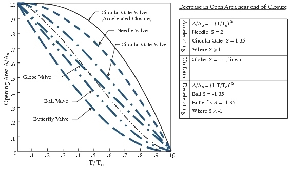
By default, several standard valve types are available, in the "valve type" field (such as butterfly, globe, needle). This essentially defines the discharge coefficient that HAMMER uses for various values of "relative closure" in the operating rule. For example, some valves may have a sharp reduction in area as they start to close (stroke) and then a slower reduction in area just before they are fully closed. Meaning, a value of 90% closure in your operating rule might not necessarily mean the valve's open area is 10% of the original area. The user can also define a user defined table of relative closure versus relative discharge coefficient, by selecting "user defined" as the valve type.

This exposes the "Valve Characteristics" attribute, which is where you would enter the table of relative closure versus relative discharge coefficient to define the characteristics of your valve. The relative discharge coefficient values are relative to the value entered for "Discharge Coefficient (fully open)". See the latter half of the video at the bottom of this article for a demonstration. Note that the discharge coefficient is "Cv", explained more here: What is the "Discharge Coefficient"?
Valve Characteristic Curves
Valve characteristic curves for the standard "Valve Types" (Ball, butterfly, circular gate, globe and needle) are based on published data (Fok, 1987). The curves have the functional form:
1 – Yk ...
where needle valves have k = 2.0; circular gate valves, k = 1.35; and globe valves k = 1.0;
or:
(1 – Y )k ...
where for ball valves, k = 1.35; and butterfly valves, k = 1.85.
More information can be found at the following paper:
Fok, A.T.K., “A Contribution to the Analysis of Energy Losses in Transient Pipe Flow”, Ph.D. Thesis, University of Ottawa, 1987.
Note: most valve manufacturers can provide the discharge coefficient(s)
Note: When modeling a valve whose initial status is "inactive", ensure that you've entered a value for the "minor loss coefficient". When computing initial conditions, the "minor loss coefficient" is used to compute headloss through the fully open (inactive) valve. This headloss is important since it is used to define the relationship between head loss and discharge as the valve closes.
Viewing Results
You can view flow, hydraulic grade, and pressure results where the valve connects to a pipe in the Time History graph in the Transient Results Viewer. If there is vapor forming at this point in the model, vapor volume can also be viewed.
Starting with HAMMER CONNECT Edition Update 3 version 10.03.04.05, you can also view results in the Extended Node Data tab in the Transient Results Viewer. This includes Valve Percentage Closure, HGL (From), HGL (To), and Flow. See this link for more information: How to view extended node transient results for HAMMER elements.
Note: As of version 10.03.05.05, if you look at the relative closure of a PRV in the Extended Node Data tab, the results may display incorrectly and 0% relative closure. The reference for this is 812024. This will be resolved in a future release of HAMMER.
Example Model
In the latest version of HAMMER, this example model can be found in the "Samples" folder within the installation folder and is called "Valve_Closure_Example.wtg". For older versions that do not have this, you can download a version of it here:
Click to Download
Note: the above model is for example purposes only. It can be opened in version 08.11.00.30 and above and you can find additional information under File > Project Properties. Also, you must be signed in to Bentley Communities or the link will not work.
Video Demonstration - transient valve closure
A video demonstration of advanced valve closure modeling is available within the HAMMER Learning path on Learn.bentley.com. See the on-demand video named "Causes of Transients - Valves". This training course is also available on our YouTube channel, and the video in question is embedded below:
Reference
- Advanced Water Distribution Modeling and Management - Walski, 2007
See Also
Gradual closure not occurring when using valve operating rule
Protective Equipment FAQ
Modeling An Initially Partially Closed Valve
Modeling Reference - Valve With Linear Area Change
Using Modulating PRVs
General HAMMER V8i FAQ