| Product(s): |
SewerGEMS, CivilStorm |
| Version(s): |
08.11.04.54 and later |
| Area: |
Modeling |
Background
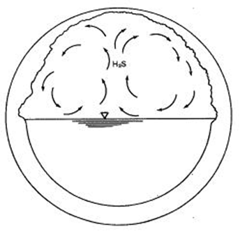
This article explains how to analyze hydrogen sulfide formation (sometimes referred to as septicity) in a sewer hydraulic model.
Hydrogen sulfide forms in wastewater collection systems when anoxic conditions exist and results in corrosion, odor and toxicity problems. The rate of formation depends primarily on the strength of the wastewater as characterized by BOD concentration (Biochemical Oxygen Demand) and rate constants for the reactions which are dependent on temperature. Hydrogen sulfide in most commonly a problem in systems with long detention times in warm weather. The hydrogen sulfide calculations assume that sulfate concentration is not limiting.
The calculations are based on the Pomeroy-Parkhurst equation for predicting H2S concentrations in a sewer network and can be used to evaluate the build-up or decay of the H2S concentration in a sewer system. The Pomeroy-Parkhurst equations give total sulfide concentration, not the individual species (H2S, HS-, S-). That depends on variety of factors and pH is one of the most important, but we can’t calculate that.
Our method is based on ASCE Manual 69, Sulfide in Wastewater Collection and Treatment Systems.
The sewer system can be gravity and pressure combined system consisting of conduits, ponds, channels, wet-wells, pumps, pressure pipes and junctions.
Note that the calculated H2S produced by the model represents the H2S concentration in the aqueous phase. The amount that escapes to the gas phase depends on the turbulence, and various coefficients in Henry’s Law.
The Pomeroy-Parkhurst equation used for the calculation was developed on steady flow conditions. Since most models using SWMM solver are of dynamic modeling, some assumptions must be made for proper application of the equation. The primary assumption is that the solver will use the average hydraulic condition for the H2S calculations. The solver determines the average pipe flow by the total flow volume that has passed through the pipe for the simulation duration, the node H2S/BOD mixing calculations will also be based on the average flows of incoming and outlet pipes.
For more background information, see the Help topic "Hydrogen-Sulfide (H2S) Modeling" and the video further down.
Modeling Hydrogen Sulfide
To analyze hydrogen sulfide formation in a SewerGEMS model, the SWMM solver must be used and various data must be input into the manholes and pipes.
The primary assumption is that the solver will use the average hydraulic condition for the H2S calculations. The solver determines the average pipe flow by the total flow volume that has passed through the pipe for the simulation duration, the node H2S/BOD mixing calculations will also be based on the average flows of incoming and outlet pipes. The pipe detention time is determined by the pipe length and average flow velocity; the node detention time is determined by the average node volume and average outlet flow.
As a result of these assumptions the model provides a steady result set for the network which represents the expected average changes.
1) Select the Explicit (SWMM) solver in the Calculation Options or Compute Center
2) Select "True" for the calculation option "Run Hydrogen Sulfide Analysis." A reasonable model run time and a small reporting time step increment (such as 0.05 hours) should be set.
3) For each manhole, enter:
H2S (Local Inflow)
BOD (local inflow)
Usually, there is very little H2S in the inflow but the presence of BOD (biochemical oxygen demand), along with sulfate, leads to the formation of H2S. For domestic wastewater, the BOD concentration may be on the order of 200 to 300 mg/L while for industrial waste, it can vary widely.
4) For each pipe, enter:
Temperature
H2S Flux Coefficient
H2S Loss Factor
5) For wetwells, enter:
H2S (Local Inflow)
Temperature
Reaction rate
BOD (local inflow)
6) Compute the model and view the computed H2S and BOD concentration in the "Results (H2S)" section of the properties. The results will not change with time. This is because the average flow conditions are applied to the H2S calculations.
H2S forms in link elements (conduits, pressure pipes and channels) and is a function of temperature. The temperature default value is 20 deg C. The H2S flux concentration is on the order of 0.0003/hr while the H2S loss rate is on the order of 0.9. These values need to be calibrated for local conditions as there can be a great deal of variation. For pressure pipe and inverted siphons, there is no loss coefficient as H2S gas cannot leave the liquid phase. For wet wells, the Reaction Rate should be on the order of 0.2/day.
Viewing Results
H2S results are considered maximum results. For that reason, the value you see in the Results section of the Properties grid or in the element FlexTables will be the result for all time steps. For the same reason, a graph of he H2S and BOD results will be a straight line.
Because of this, you can often simple use numerical values from the FlexTables to view results. These results could be included in a Custom Report.
The results can also be included in Element Symbology as color coding or annotations.
H2S results at a node are calculated based on the weighted average of upstream pipe flow rate and H2S value. Conduit size only affects H2S change from conduit upstream to downstream. For storage node (wet well), H2S will increase based on the input and size of the wet well. Detention time of storage node is calculated by dividing storage volume by flow rate. The larger storage volume, the longer detention time and higher H2S increase. Local H2S injection and inflow are also included in node weighted H2S calculation. If you have flow coming into a node from more than one pipe, the results will vary based on the input and H2S concentration from both sources. If the H2S in one branch is relatively small, little or no change in H2S may be reported compared to inflow from a larger main.
If you see results that say N/A, this can occur if the H2S Loss Factor in a pressure pipe is set to zero. See the following link for more information: Troubleshooting "N/A" results in H2S Modeling for pressure pipes.
Troubleshooting
- Detention time results at a manhole will typically be reported as zero. This is because the SWMM solver ignores manhole storage. This assumption is viable because the detention time of for manholes that are not surcharging is essentially zero. Even a surcharging manhole would see a detention time that is so small that it is essentially zero.
- If unexpected results are seen such as a sudden drop in average H2S along a series of pipes, it is possible that convergence problems occurred. If using version 10.03.04.53, please contact Support for the latest cumulative patch set for this version, or upgrade to a newer version when available, which is planned to have improvements to increase the maximum number of H2S convergence trials. A similar patch is also available for version 10.04.00.158.
See also : Troubleshooting "N/A" results in H2S Modeling for pressure pipes
Video