| Product(s): |
WaterGEMS |
| Version(s): |
10.00.00.55 and Later |
| Area: |
Modeling |
What it Does
The EPS Fire Flow Analysis tool automates specific fire flow results. It provides a way to run a range of flows on each fire flow node, only at the time of minimum pressure from an EPS, and run the full EPS up to that point.
Benefits
Some regulatory agencies require this type of analysis (eg. Australia).
Applicable Products and Version
The EPS Fire Flow Analysis tool is available for WaterGEMS version 10.00.00.55 and later. It is not currently available for WaterCAD.
How to Access
Starting with WaterGEMS and WaterCAD CONNECT Edition Update 2, this tool now ships with the application. You can browse to C:\Program Files (x86)\Bentley\WaterGEMS or C:\Program Files (x86)\Bentley\WaterCAD\x64 to file the file called Haestad.EPSFireFlow.exe to access this tool. If you are using WaterCAD, you will go to the same location, only clicking the WaterCAD folder instead.
If you have an older version, first make sure you are using WaterGEMS or WaterCAD version 10.00.00.55 or greater. Click here to see how to determine the version you are using.
Next, Determine if you are using the product in 32-bit or 64-bit mode. To check, go to: File > Help > About WaterGEMS. The bottom of the dialog will show either 32-bit or 64-bit.
Download:
Install:
1. Download and extract the following .zip file:
2. Copy the extracted "Haestad.EPSFireFlow.exe" files as shown below.
Copy the file from the folder “x86” to the following folder:
C:\Program Files (x86)\Bentley\WaterGEMS\
Copy the file from the folder “x64” to the following folder:
C:\Program Files (x86)\Bentley\WaterGEMS\x64\
3. Run the "Haestad.EPSFireFlow.exe" file from the x64 subfolder to run the 64-bit version.
How to Use
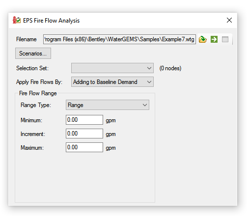
The tool is very simple to use and provides minimal options. When running the "Haestad.EPSFireFlow.exe" file the following dialog will appear.
Note: if there is an issue starting the tool then try right-clicking on the executable file and selecting “Run as Administrator”. Also ensure that the version of the tool matches the version of WaterGEMS that you have installed (check under File > Help > About).
1. Select the model
Click the Open button to select a WaterCAD or WaterGEMS hydraulic model to use for the analysis.

Once the project is open, there are options that must be specified before calculating the EPS Fire Flow.
2. Select the scenario(s)
a. Click the Scenarios button to display the "EPS Fire Flow Scenario Selection" dialog.
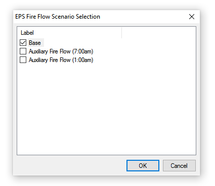
b. Select at least one EPS scenario, and then click OK.
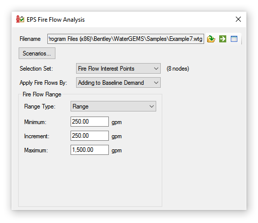
3. Choose a selection set
Choose a selection set from this dropdown list to use for the EPS fire flow analysis. The junctions and hydrants in the chosen selection set will be included in the analysis. Each of these junctions and hydrants will have the fire flows applied (during the time when the pressure is lowest) for each fire flow included in the range.
Note:
- This option is required.
- The number of fire flow nodes in the selection displays to the immediate right of the drop-down box.
- The number of nodes includes both inactive and active nodes.
- The “Is Active?” state of the node is determined during calculations and inactive elements are ignored.
4. Specify how fire flows will be applied
In the "Apply Fire Flows By" dropdown, specify if the fire flows will be applied by adding to the baseline demand or if they will replace the baseline demand.
5. Select a range type
Range: This allows a Minimum, Maximum, and Increment to be entered to establish the range of flows that will be tested for each fire flow node in the selection set.
- The minimum must be greater than 0.0 and less than the maximum flow.
- The difference of the minimum and maximum flows must be equally divisible by the increment.
User Defined Flows: This will establish the range of flows that will be tested for each fire flow node in the selection set. When this is selected then flows can be manually added and deleted in a tabular format.

Calculation Steps
To calculate the EPS fire flows click the Compute button to the right of the Open button in the toolbar.
Here are the steps performed by the tool.
- Calculate each scenario.
- Determine the times during the EPS scenarios when active node in the selection set is at its respective minimum pressure.
- Calculate a hydrant flow curve for all active nodes in the selection set for the scenarios selected. Each hydrant flow curve will be created at the time each node is at its respective minimum pressure.
- Use the hydrant flow curves to find the residual pressures for each of the user-specified fire flow values, for each combination of the specified scenarios, nodes and times.
See: Help Topic “Hydrant Flow Curve Editor"
Data Validation
The data is validated when computing. An error will appear if any of the following are true:
- One or more selected scenarios is not EPS.
- There aren’t any active junctions or hydrants are in the selected fire flow nodes selection set
- The minimum fire flow is less than zero or greater than the maximum fire flow
- The maximum fire flow is equal to orless than minimum fire flow
- Increment is zero or not an exact factor of the difference between the min and max
- One or more scenarios fail to compute (An initial check is made by running each selected scenario as-is).
Results
The results are presented in a table once the calculation is successfully completed. If the validation fails, no results are displayed until the issues reported are resolved.
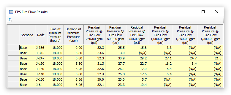
The first three columns are always available showing the scenario label, the fire node label and the time at minimum pressure.
The remaining columns are based on the flow range specified. The hydrant flow curves (created for each combination of scenario, node and time) are used to interpolate the residual pressure for each flow specified in the fire flow range. If the interpolation returns a negative pressure, (N/A) is shown in the table. Otherwise, any pressure greater than zero is displayed.
Units
The units used in the tool are based on the settings of the open project. You can change units by right-clicking the unit next to the minimum, increment and maximum fields on the main dialog and clicking “Units and Formatting”. You can change the units of pressure in the results table by right-clicking the column header and clicking “Units and Formatting”.
Other Notes
No changes are made to the project opened. When closing the tool or opening a different project, the project that was previously opened (if there was a project opened) is not saved.
See Also
EPS (Extended Period Simulation) Fire Flow Analysis
Understanding Automated Fire Flow Results