| Product(s): |
WaterGEMS, WaterCAD, SewerGEMS, SewerCAD |
| Version(s): |
CONNECT Edition |
| Area: |
Modeling |
Background
It is often desirable to keep a hydraulic model in sync with its related GIS, to have a complete "digital twin". For example as things are changed in the GIS, you will want to bring those changes into the hydraulic model, so that you have the most accurate depiction of the system. Conversely, you may also make changes to the hydraulic model, and you may or may not want those changes back into the GIS. In some cases the hydraulic model is the "source of truth" for hydraulic parameters such as calibrated roughness, whereas the GIS is the "source of truth" for the assets themselves, pipe break history, etc.
Each system is set up differently and may need a different workflow to utilize the many tools available in Bentley's water infrastructure products to keep things in sync.
Available Model Sync Features
The following tools and features are related to Model/GIS synchronization and are available in the latest versions:
ModelBuilder - the primary tool used to import and export data between an external source and a hydraulic model. Provides many different options to cater to different use-cases. See more here.
Some minor, related features include the Selection Set ability to update or sync out a subset of elements, the WHERE Clause ability for filtering what is imported and Table Duplication which enables you to import a source table multiple times with different options. The latter two can be used for example to import multiple element types from a single table (for example if you have valves as a single table/feature with a field to differentiate the type, and want to bring in the separate element types PRV, PSV, FCV, etc.) See more here.
GIS-ID - A labeling system that can be used by ModelBuilder to keep a model in sync with a GIS without having a 1:1 match. A single model element can link to one or more GIS-IDs or vice-versa. Provides many different options to cater to different use-cases. Note that this feature has been enhanced and made robust over the course of many versions and can account for complex relationships like 1:many and many:1 geometry.
GIS-ID Control Center - This enables you to view and edit all GIS-IDs for all elements, in table format. (similar to the Demand Control Center for demands).
Spatial Join - A mapping method in ModelBuilder, used to connect components in your GIS to model elements by way of spatial proximity instead of a key field.
Snapshots - A tool in ModelBuilder to help you track changes between model synchronization. Enables you to quickly see what has changed, and accept or reject changes during model updates. See more here.
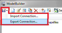
ModelBuilder Connection Export - You can export the ModelBuilder configuration as a file, which you can save along with the model for potential future re-use on a different computer. This can also be done in batch for automated workflows. See more here.
Change Tracking - An optional audit of changes made to the model. Can be useful to review before synchronization. See more here.
Model Synchronization Workflows
As mentioned above, every system and every GIS is set up differently, and every user will have different needs regarding synchronization between the GIS and the hydraulic model. Here are some of the use-cases that can arise, and the tools you might use in those situations:
Initial model creation from the GIS
When you first create your model, there are a few things you can do to set yourself up for success with future model synchronization. If you already have a model created, skip to the next section.
- Connect to the GIS in a new ModelBuilder run. If your GIS is stored in a geodatabase, you can connect directly to it when working in the ArcMap integrated platform (available in SewerGEMS, WaterGEMS and HAMMER). Otherwise, you could export the GIS to Shapefile format and connect to that in ModelBuilder by using the "ESRI Shapefile" source type.
- Import all features at once. In the first step of ModelBuilder, select all the different layers with elements you would like to import. Hold the CTRL key on your keyboard to multi-select the layers or even multiple shapefiles (for example pipes, junctions, pumps, tanks, etc). If you only import the pipes first, and then the nodes later, the initial pipe import will automatically create end nodes, which will then overlap subsequently imported node elements.
If different nodes are stored in a single table in your source (for example PRVs, PSVs and FCVs as a single valve element with a field differentiating the type), you can utilize the WHERE clause field along with the duplicate table feature, to bring in each one as a separate element types. See more here: Using the WHERE clause and Duplicate option in ModelBuilder
- Choose the option to Establish Connectivity using Spatial Data. This ensures that pipe (polyline) endpoints "snap" to nearby nodes, based on spatial proximity. This way, you do not need to map a start/stop node field, as the connectivity is inferred. Make sure the "Tolerance" is large enough to snap endpoints in cases where drawing imperfections occur in the GIS, but not large enough to cause pipes to connect to the wrong nodes.

- Use the GIS-ID feature as the key field to establish the connection between the GIS and the model. This enables you to retain this connection even in one-to-many or many-to-one situations. For example if you use Skelebrator in the hydraulic model, it will remember that a single pipe actually represents multiple pipes in the GIS. Or, if you split a pipe for example, it will remember that the two pipes in the hydraulic model actually represent a single pipe in the GIS. This will be retained for future model synchronization. Be sure to choose the field in your GIS that has unique identifiers, such as GlobalID. Note that this feature has been enhanced and made robust over the course of many versions and can account for complex relationships like 1:many and many:1 geometry.


- Use the Snapshots feature (available in CONNECT Edition Update 1 and greater) to establish the initial snapshot of the state of the GIS when you first import the model. Snapshots will help you on subsequent model synchronizations, so you can better track and manage changes since the last synchronization. Check the box for "Use Snapshots to track changes...", then leave "use latest snapshot" blank (since you have not established a snapshot yet)

- Once the model is built, thoroughly inspect connectivity to identify any problems that need to be addressed. Problems may need to be resolved on the GIS-side, or may require an adjustment to the ModelBuilder options. Make use of Network Navigator Queries to look for problems, and see the following article for additional tips: Preparing GIS data for use in the hydraulics and hydrology products
- Consider exporting the ModelBuilder run to a .MBC file to store along with the model. This can be helpful in the future if you happen to lose the ModelBuilder connection from your initial import - the ModelBuilder connections seen in the ModelBuilder manager are stored in a special XML file in the Windows user profile so as to be available in any model, but if you move to a new computer, rebuild your Windows user profile, or have a need to reinstall Windows, the data could be lost if you do not export it. See more here.
- The batch import functionality can be used to import multiple .MBC files in ModelBuilder via command line, for more efficient model building workflows. See more in the "ModelBuilder Connection Batch Import" section of this article.

Updating the model based on changes in the GIS
If you need to update a hydraulic model based on changes in the GIS, there are several possible workflows, depending on your situation.
Consider starting out by focusing on a small pilot study area, rather than trying to tackle the entire model at once. Pick a location in your real model that demonstrates many of your anticipated challenging situations, or set up a fabricated small model with those situations. This will enable you to more easily understand how to configure your ModelBuilder connection for a successful synchronization of the full model. This is especially useful in case where the above suggested initial setup workflow was not followed. If you did use the above workflow (most notably, GIS-IDs and Snapshots), then you may not need to set up a pilot study.
- Ensure the model is using GIS-IDs - Ensure all elements currently in the model that are based on the GIS have GIS-IDs. You can check this by looking at the "GIS-ID collection" field near the top of element properties, or by opening the GIS-ID Control Center (under Tools > Tools). If you do not see anything listed in the GIS-IDs collection, then your model is not set up to use GIS-IDs yet.
- If you followed the above suggested workflow, your model should be set up with GIS-IDs and you should see them listed.
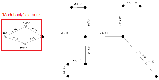
- If you added new elements in the hydraulic model that you do not want the synchronization workflow to "touch", then they should not have GIS-IDs. For example the representation of a pump station may look different in the hydraulic model (for example reservoir > multiple parallel pipes > pumps > multiple parallel pipes > junction) when compared to the GIS representation. To ensure that these elements are not removed by the model synchronization, check that a GIS-ID is not entered for them. GIS-IDs are show in the GIS-ID collection field, or you can access them via the GIS-ID Control Center. For example if you have a selection set of these "model-only" elements, you can double click the selection set to select them, open the GIS-ID Control Center (under Tools > Tools), then click the filter button and choose Open on selection. Then, clear any GIS-IDs that show up for these elements.
- If you do not currently have GIS-IDs established in your model, you will need to populate them. The method to do this depends on the naming system used for unique identifiers in your GIS. See: How to populate or update an existing model with GIS-IDs
- If your element labels match the GIS-IDs should be (for example a pipe (model) with label "12345" has a unique ID (GIS) of "12345"), then you can establish GIS-IDs via copy/paste:
- Select hydraulic model elements that should be "touched" (exclude "model-only" elements - see 1aA above) Double click the selection set to select those elements.
- Open the GIS-ID Control Center (under Tools > Tools), filter > open on selection (filter it to only show the elements that can be "touched")
- Copy/paste from Label field to GIS-ID field. Right click the label column, choose "select column", click the Copy button, select the first cell in the GIS-IDs column, click the Paste button. Ensure that the data pasted correctly (and lines up with the label column).
- Confirm that "model-only" elements do not have a GIS-ID (see 1aA above)
- If your element labels are different from the GIS-ID system used in the GIS (for example a pipe with label "P-1" (model) has a unique identifier of "12345" in the GIS), then you can try to populate the GIS-IDs based on spatial proximity using the Spatial Join option in ModelBuilder (available in CONNECT Edition Update 1 and greater)
- Create a selection set containing only the elements that you want ModelBuilder to be able to "touch" (exclude "model-only" elements - see 1aB above)
- Set up a new ModelBuilder connection (including a table for each element types) with options set as they were when you created the model, except when you get to the "Specify Additional Options" step, choose the bottom option, to "Map elements spatially to closest matching geometries (spatial join)".
- In the final step, choose the selection set created in step i. This will ensure that "model-only" elements will not receive a GIS-ID (see 1aB above.)
- Set up a prototype for new pipes - If you will be importing some new pipes from the GIS and will not be mapping certain properties such as roughness, you may want to create a new Pipe prototype and enter an appropriate roughness for "new" pipes. Prototypes establish the default properties, for newly imported pipes, if those properties are not mapped/imported from the source. If you will have multiple different materials and roughness for new pipes, use the method further below under item #4
- Reuse or create a new ModelBuilder run - If you had created the model using ModelBuilder and still have the connection available in the ModelBuilder manager, open the connection and go through each of the steps as follows. If you had moved the model to a different computer (or reinstalled after upgrading or reinstalling the operating system, for example), then the previous ModelBuilder run will no longer be present in the ModelBuilder manager and you will need to configure it again, unless you had exported the connection as a .MBC file (see step 7 above from the suggested workflow for an initial model build)
- "Specify your Data Source" step: ensure that all layers for all element types are set to be imported. Use the CTRL key to multi-select when browsing to the data source, and use the WHERE clause field if needed as seen here.
- "Specify Spatial and Connectivity Options" step:
- Create Nodes if none found at pipe endpoint
- If all pipes in the GIS have discrete nodes at all endpoints, this can be unchecked.
- If there may be cases where a new pipe in the GIS does not have a point (that you would be importing as a junction) at its endpoint, then check this option, to automatically create a node at the endpoint. For example a section of a pipe that was replaced due to a pipe break. Pipes in the Bentley Water Infrastructure products require a connected node at each end. Note that in this case, the automatically created node will not have a GIS-ID.
- Establish Connectivity using spatial data - check this box if you are importing a geodatabase or Shapefile where spatial information is built in. This way, newly imported or updated elements will automatically connect without having to explicitly map the start and stop node for pipes.
- "Specify Element create/remove/update options" step:
- Add Objects to Destination if missing in Source - check this box, to ensure that new elements in the GIS are added to the model
- Remove Objects from Destination if missing in Source - check this box, to ensure that elements that are no longer in the GIS are removed from the model (see note further below regarding "model-only" elements that you want to preserve and not delete.
- Update existing objects in destination if present in source - uncheck this box if the hydraulic model is considered to be the "source of truth" for hydraulic properties of elements. Meaning, if your GIS is used to keep track of where the assets are and basic properties like installation year, but the hydraulic model is used to keep track of properties like calibrated roughness, valve status, demands, etc. Unchecking this box in this case will ensure that existing elements in the model are not "touched" for fields that you will map for the purpose of populating new elements.
- Create referenced objects automatically? - uncheck this box if you need to uncheck the "Update existing objects..." box.
- "Specify Additional Options" step:
- Map Elements by key field - select the "GIS-ID" option. See explanation further above under step 1 (ensure the model is using GIS-IDs)
- When removing objects from destination if missing from source, only remove objects that have a GIS-ID - Ensure that this box is checked; this is important as it enables you to "protect" elements that do not have a GIS-ID (such as "model-only" elements that you don't want to have a match to the GIS), and still be able to delete objects whose GIS-ID is no longer in the GIS (for example a single pipe that is now multiple separate pipes in the GIS).
- "Specify Field Mappings" step:
- Key Fields - for each layer (element type) on the left side, choose the field in the GIS that contains your unique ID system (your GIS-ID)
- Field mapping (table at bottom) - if the hydraulic model is considered to be the "source of truth" for hydraulic properties of elements, you may only need to map the material and installation year (or age), and/or other basic parameters. If the GIS contains attributes that you need to import for new elements (elements that are in the GIS but not yet in the model), then you can map those too - because you unchecked the "Update existing objects..." setting (see 3cC above), ModelBuilder will not change those mapped fields for elements that are still matched between the GIS and the model.
- "Specify snapshot settings" step (available in CONNECT Edition Update 1 and greater)
- If you had followed the above suggested workflow ("Initial Model Creation from the GIS") - check the box for "Use Snapshots..." and the box for "Import only what has changed...", then select the snapshot from the dropdown (if you stored it in another location, choose "Specify a custom location..." and browse to it). This will enable you to only import things that have changed since the last synchronization. Click the "Preview Changes" button to review details of what has changed, and accept or reject as needed. See more here.
- If you did not already establish the initial snapshot - check the box for "Use Snapshots...", to establish a snapshot of the GIS at the time of this synchronization. This will be helpful for future Sync-Ins, so it is more clear to you what has been changed since the last update. You can leave the "use latest snapshot" field blank if this is the initial snapshot.
- "Create model now?" step:
- Choose "Yes" for "Would you like to build a model now?" and leave the "scope" as "entire model".
- Choose to create a selection set for newly created elements. This will help later, if you need to populate roughness for newly created pipes.
- Review the Summary at the end of the ModelBuilder run and check for anything unexpected. You may also want to note the names of junctions that were deleted from the model (see item #5 below)
- Populate pipe roughness for newly added pipes - In some cases, you may have had calibrated roughness for pipes which were removed and replaced due to a change in the GIS. For example a single pipe which is now three pipes in the GIS due to a small segment in the middle being replaced due to a pipe break (see example below). It may be desirable to retain the original roughness of the two pipes that represent the original pipe, and use a new roughness for the new segment of pipe. If the original pipe was deleted and replaced with multiple new pipes with new GIS-IDs, you can potentially use the installation year of the imported pipes as a way to re-establish calibrated roughness for the older existing parts of the pipe, and use a smooth "new" roughness for new parts of the pipe. Typically roughness is calibrated based on age and material, in which case pipes of a certain age and material will have a certain roughness. One way to accomplish this is through a series of filter + global edit to the pipe flextable:
- Look at other/existing calibrated pipe roughness in the hydraulic model to determine the roughness for a given material and age.
- Double click on the selection set that was created at the end of the ModelBuilder run, for newly created elements (3gB above)
- Right click in the drawing, choose Edit group, then open the Pipe flextable. This will filter it to only show newly imported pipes, which may need to have roughness updated
- Ensure that installation year or age is added, along with material and roughness (typically Hazen-Williams C factor)
- Perform an additional filter on installation year/age and material, to view all pipes in the first grouping of roughness
- Right click on the roughness column, choose global edit, then Set the roughness to the respective value for its material and age group
- Repeat steps e and f for each combination of material and age group
- Pipes with a recent installation year may not have a reference roughness, and you may need to either assume a smooth roughness coefficient, or you could keep them as the default roughness based on the pipe prototype you configured in step #2.
- Re-populate demands for deleted nodes - in some cases, junctions that previously had demands, may have been deleted from the model due to the "Remove Objects from Destination if missing in Source" setting.
- If it is feasible to review the list of deleted nodes from the ModelBuilder summary, you could manually re-add the demands.
- Or, if you had originally used LoadBuilder to import demands based on spatial information from shapefile consumption data, re-run LoadBuilder to re-add the demands:
- First, clear out all existing demands by either creating a new base demand alternative and assigning it to the scenario in question, or open the Demand Control Center, highlight all rows and click Delete.
- Run LoadBuilder with the same configuration as when you first loaded the model demands. At the end of the LoadBuilder run, you can re-assign the demand patterns.
- Re-apply any necessary demand adjustments, via global edit to the base demand in the Demand Control Center. This may not be necessary, if you had configured adjustments using the Active Demand Adjustments calculation option.
Example workflow (updating model based on changes in the GIS)
The below example is a case where a single pipe in the hydraulic model is now three pipes in the GIS, because a segment in the middle was replaced due to a pipe break. The hydraulic model also contains some "model-only" elements; a pump station seen on the left side, which does not have a detailed representation in the GIS. In this case, you want to keep the model in sync with the GIS and update it with the changes, but you do not want your pump station to be "touched", and you want to re-establish calibrated roughness for the segments of pipe next to the newly installed segment.
Hydraulic Model:
GIS representation:

Model, after update:

Updating the GIS based on changes in the model
Changes from the model to the GIS typically consist of corrections that need to be made to the GIS such as errors discovered while creating or calibrating the model. Those changes should be communicated to the GIS team to integrate into the GIS. Modelers typically do not have permissions to directly sync-out from the model to the GIS.
Minor changes could be communicated by email for example ("correct this diameter").
For more extensive changes, the model element data can be customized in FlexTables and that data can be exported to Shapefiles.
The ModelBuilder sync out feature provides a way to update source files with changes made. That data can then be reviewed and integrated into the GIS.
You can use Change Tracking to review recent changes to the model, create a selection set of those elements if needed, and sync out by that selection set via ModelBuilder, or (ex: if you don't have access to write to the GIS), communicate those changes to the GIS department.
Typically system designs and extensions created in the model would not be added to the GIS until they are constructed. The GIS team typically gets new as-built additions and adds them to the GIS which is when GIS-IDs are assigned. In some cases, the GIS team is lagging behind on these updates. Modelers may need to add recently constructed elements to the model that have not yet made it into the GIS. If it is known that something will eventually be added to the GIS then it is important to keep the model elements in-sync with the GIS.
What if I replace valve nodes with Isolation valves?
If you had originally imported valves as nodal valve elements (such as a GPV or TCV) connected to pipes, you can use the Inline Isolation Valve Replacement feature in Skelebrator to convert the valves to isolation valves. One of the benefits of this is that you can reduce model complexity and the number of pipes - instead of two pipes connected to a valve node, you would have an isolation valve associated with (attached to) a single pipe.
If you take advantage of the GIS-ID feature to keep your model in sync with your GIS, using the inline isolation valve replacement tool will result in a single pipe with both GIS-IDs from the two former pipes. So, if a change happens to these pipes in the GIS and you perform a sync-in (from the GIS to the model) in ModelBuilder, the single pipe in the model will receive the update for the two pipes from the GIS. If both of the pipes were changed in the GIS, a ModelBuilder sync-in will adopt the "last one wins" principle to determine which of the two changed pipes in the GIS are synchronized to the one pipe in the model. For this type of workflow, it is recommended that you use the Snapshots feature in ModelBuilder.
If you use WaterCAD (and thus do not have access to Skelebrator), you can still manually reconnect the pipe, add the isolation valve and modify the GIS-IDs accordingly.
See Also
How to populate or update an existing model with GIS-IDs
Using the Sync Out function to update source files using ModelBuilder
Building and updating a model using ModelBuilder
Customizing FlexTables for viewing and reporting data -- Moving, adding, and removing columns
(Virtuosity Blog) Real-Time Model Maintenance