| Product(s): |
SewerGEMS, SewerCAD |
| Version(s): |
CONNECT Edition, V8i |
| Area: |
Modeling |
Overview
This article explains possible methods to model grinder pumps (such as "E/One" style pumps) in a pressure sewer system in SewerCAD or SewerGEMS.
Background
A grinder pump is generally used to convey sewage from the source (typically a house connection) to sewer main. Typically, this pump system consists of a sump/storage well, the pump itself and an instrument panel. The function of the “grinder” pump is to pump wastewater from the customer’s sump into the pressure sewer system and grind solids to that they will not clog sewers.
Generally, these pumps are installed for individual houses or commercial buildings connecting to a common sewer main. In a locality such grinder pumps are useful in conveyance of sewage to the main sewer which would ultimately terminate at the treatment plant.
There are two general categories of grinder pumps:
1. Semi-positive displacement pumps characterized by the E/One style pumps and
2. Small centrifugal pumps manufactured by numerous companies.
Solution
For this article we are considering the “E/One” grinder pumps commonly used in designing sewerage networks for localities. The “E/One” grinder pumps work on the “E/One Probability Method” which provides data to run the pumps simultaneously. The E/One pumps have a near vertical Head vs. Discharge curve which enables them to run over multiple points of operation. This ensures that multiple pumps can run simultaneously efficiently over a range of discharges.
Grinder pumps may be either positive displacement or centrifugal type. The E/One grinder pumps are semi-positive displacement pumps which discharge whatever their design flow is without much dependence on pressure whereas centrifugal pumps operate on their defined pump curve.
For centrifugal pumps, the user can assign a flow, HGL or an effective pump curve for each node. The effective pump curve approach is the most accurate. Obtain a typical pump curve and combine it as you would for any other pumps in parallel, i.e. keep the same head values and multiply flow by the number of running pumps.
For E/One pumps or those using similar technology, the E/One Probability Method provides a table defining the maximum number of grinder pumps operating daily (Table 3, Low Pressure Sewer Systems Using Environment One Grinder Pumps).
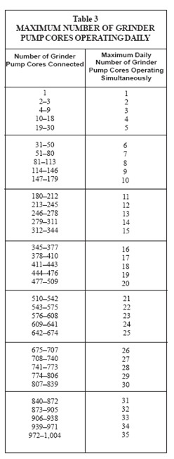
Source: E/One Pumps, LPS Design
To model multiple grinder pumps in a sewer system the above table needs to be converted into an Extreme Flow Table which will govern the flows (inflow/loads) in the sewer system.
Converting Data to Extreme Flows Table
The Extreme Flows Factors can be used with the GVF-Convex Solver available in SewerGEMS and SewerCAD.
Note: If dynamic solvers (Implicit and Explicit) are used to design the pressure sewer system, the user has to set up inflow hydrographs for each of the nodes and then define them in SewerGEMS (which has both the dynamic solvers).
From the above Table 3, the values of number of cores connected and maximum daily running cores are extracted and analyzed to develop the extreme flow factors.
| No. of grinder pump cores connected |
Max. number of pumps operating simultaneously |
| Min |
Max |
| 0 |
1 |
1 |
| 2 |
3 |
2 |
| 4 |
9 |
3 |
| 10 |
18 |
4 |
The above table is just an expanded form of Table 3 to simplify the understanding of the maximum simultaneous operation of pumps;
| No. of Pumps |
No. of maximum simultaneous operating pumps |
Extreme Flow Factor (Col2/Col3) |
| 1 |
1 |
1 |
| 2 |
2 |
1 |
| 3 |
2 |
0.67 |
| 4 |
2 |
0.5 |
E.g.: As per Table 3, for 4 pumps set up on field a maximum of 2 pumps can be operating simultaneously. Hence the extreme flow factor is 2/4 = 0.5
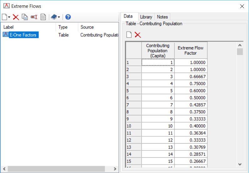
The above table can be expanded to include all the ranges provided in Table 3.
This table can be setup as an extreme flow method which the software will follow to decrease the peak flow as flow moves downstream. The table can be prepared in Excel and copied in the Extreme Flow Setup.
Alternatively, it can be converted into an equation. We have already done this in our book "Wastewater Collection System Modeling and Design" on pages 474 and 475. The coefficients for the equation depend on things like flow per pump and people per pump.
Using a table to define the extreme flows is preferred as there is no limit on the number of pumps that can be configured. This means that the computed flows from SewerGEMS/SewerCAD will always match the flow calculated by the E/One Probability Method. On the other hand, if the equation is used you may get some fluctuations in values as they do not conform to a continuous function.
Setting up the model
For the extreme flow setup to function, the system must be modeled as a gravity system with bolted manholes rather than a pressure sewer system with pump elements representing the grinder pumps.
In pumping hydraulics, the pressure solver computes the flows in the system based on actual flows which may exaggerate the downstream flows and may not conform to the extreme flow setup.
If the system is designed as a gravity system with bolted manholes, when the system is surcharged, there won’t be overflow due to the bolting and the conduits would behave as pressure pipes simulating a pressure sewer system.
Setting up the grinder pumps
For a small locality there might be hundreds or thousands of houses and it will be practically time consuming to model hundred to thousand individual pump elements based on the H vs. Q provided in the E/One Manual.
In SewerGEMS/CAD the number of contributing grinder pumps can be set up as “Loading Unit Count” for a manhole.
E.g. Suppose 5 houses having 5 grinder pumps respectively, are contributing or connecting to a common manhole (of the trunk/main sewer line), then the “Loading Unit Count” at that manhole can be 5.
Based on the type of grinder pump selected the “Unit Load” can be kept as 15 or 11 gpm which is as per the E/One Design Manual. The E/One Manual assumes fixed flow for the pumps, but the user can define the pumps as per the project requirements.
Note: The method described above works well for the GVF-Convex Solver. If dynamic solvers (Implicit & Explicit) are used, the results might be unstable. In such a case, the user would have to develop inflow hydrographs for each of the nodes and define them in SewerGEMS (which uses both these solvers).
Response to Power Outage
One of the worst cases for a pressure sewer system occurs immediately after an extended power outage. In this situation, when the power is restored, most sumps will be full and many (if not all) of the pumps will start simultaneously. This can result in very high pressures. It is worthwhile to check the pressures during this situation although it is usually not necessary to size pipes to carry all the flow through all the pumps simultaneously.
FAQ
Q: In the absence of a pump element how will sewage flow into the system?
A: The HGL at the manhole will be as per the loading defined for that manhole.
Q: How can I determine the pump head? (for the unmodeled pump)
A: To determine the head that the pump would be delivering based on the assumed inflow, the suction head needs to be subtracted from the HGL at the manhole after computing the model. The HGL you see at the manhole is the discharge HGL from the pump, so in order to know how much head the (unmodeled) pump would need to add, you’d need to know what the suction HGL is, which would be the wetwell water surface elevation.
Let’s say for example the computed manhole HGL is 100 ft and you know the wetwell average water surface elevation is 60 feet. The total head that the (unmodeled) pump would have to add is 100-60 = 40 feet.
See also: How do I find the Total Dynamic Head (TDH)?
Q: Does the loading count have to be “lots”? Can “population” be used?
A: For the particular E/One Probability Method, the pump cores/lots serving a manhole is considered as “Loading Unit Count”. Population can be used when you don’t know the number of grinder pumps connecting to the manhole.
Sample Model
The sample model available at this link contains a model setup using the extreme flows setup. Supporting files contain the extreme flow factors in excel and the E/One Design Manual.
See Also
Forum Discussion
Using Extreme Flow Factors
Wastewater Collection System Modeling and Design