| Product(s): |
HAMMER |
| Version(s): |
08.11.XX.XX and higher |
| Area: |
Modeling |
Overview
This tech-note discusses how to configure the Surge Tank element for transient analysis in HAMMER.
Background
A Surge Tank (also known as a “Stand Pipe”) is a surge mitigation device which can be modeled in HAMMER as a “Surge Tank” element. The surge tank supplies stored fluid (water) when pressures drop in the pipeline and takes fluid, when pressures increase (in case of two-way type).
The Surge Tank is a non-pressurized type of tank i.e. the free water surface of the tank is open to atmosphere. The normal water level is typically equal to the hydraulic grade line at steady state. A surge tank can also overflow and the user can specify the weir coefficient for overflow (see Overflow section below). If the water surface elevation is equal to the system hydraulic grade, the surge tank may need to be constructed very tall, with supports such as guy wires.
Note: if you are interested in a pressurized tank, see: Modeling Reference - Hydropneumatic Tanks
Surge Tank vs. Regular Tank element
The surge tank element is treated the same as a regular tank element during a transient simulation in HAMMER, except it has a few more options that are not available for a regular tank:
- Ability to model overflow via the weir coefficient and weir length fields.
- Ability to model a built in check valve in the inlet (via the Has Check Valve field), also known as a "one way surge tank".
- Ability to model inlet orifice headloss and differential orifice, via the orifice diameter, headloss coefficient and ratio of losses field.
- Ability to model a differential surge tank (via the surge tank type field) which is a specialized type of surge tank (see more below)
You can read more about these features further below.
For a simple, two way surge tank with no differential inlet orifice, it will be calculated the same as a regular tank element, as long as an overflow condition does not occur.
Surge Tank Type
Surge Tanks can be of two types; simple or differential
Simple Surge Tank
A simple surge tank can operate in three modes under a transient analysis; normal when the tank water level is between the top and the connecting pipe(s) at the bottom; weir overflow when the tank water level is at the top in overflow condition; and drainage when the tank water level is at the elevation of the connecting branch(es). A simple surge tank can be a one-way or a two-way surge tank.
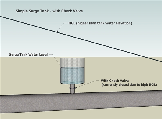
One-way Surge Tanks
A one-way surge tank is a relatively small conventional surge tank, with a check valve in the connecting pipe, or riser, that only allows flow out of the tank. The tank water level is maintained by an altitude valve bypassing the check valve. The tank is located at the high point to supply water and prevent water-column separation. However, one-way tanks provide no upsurge protection to the system because no flow is allowed back into the tank. This is modeled in HAMMER by selecting "True" for the “Has Check Valve?” field.
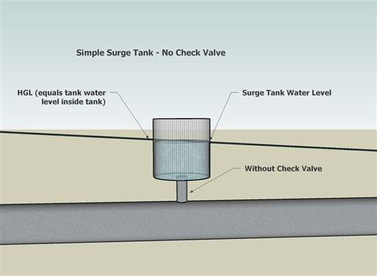
Two-way Surge Tanks
A two-way surge tank allows stored water to flow out in the event of low pressure developing in the pipeline but also allows water to flow into it in times of high transient pressures. two-way surge tank controls transients by converting stored potential energy in the elevated water body inside the tank into kinetic energy, which supplements flow in the piping system at critical times (or vice versa, for pipe flow into the tank) during periods of rapid flow variation. The tank is normally located at the pumping station or at a high point in the system. This is modeled in HAMMER by selecting "False" for the “Has Check Valve?” field.
Differential Surge Tank
A Differential surge tank is a specialized surge tank within a larger tank which provides a fast response. This type of a surge tank contains a differential orifice installed at the inlet riser which serves two functions, it doesn’t allow the surge tank to fill up quickly during a high pressure event by causing a large enough headloss to dissipate the transient energy but at the same time, flow can leave the surge tank quickly (with little headloss) in case of a low pressure event.
To model a differential surge tank, select "Differential" from the "Surge Tank Type" attribute of the surge tank node element.
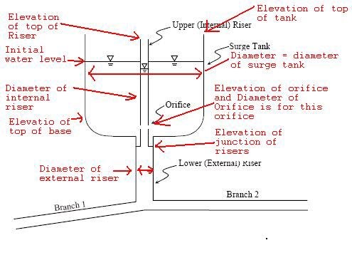
Differential Surge Tank Attributes
See the red text in the diagram below, which clarifies which dimensions each of the attributes represents. This additional fields will appear when the surge tank is set as Differential.
Multiple orifices between internal riser and tank
If you have more than one orifice between the internal riser and the outer tank (for example multiple equally sized orifices at the same elevation), you will need to determine an equivalent orifice size since there is only a single field for the "Diameter (Orifice)". To do this, calculate the flow through a single orifice at a given example head (based on a typical water level), multiply it by six (assuming six equal sized orifices at the same elevation on the side of the internal riser), then use the resulting flow to solve for diameter keeping head the same. This can be done for example using Bentley FlowMaster. This will provide an equivalent diameter that should result in the same flow vs. head characteristics as the set of multiple orifices.
Differential Surge Tank Behavior and results
There are different modes of operation for a differential surge tank. For "normal" operation, the tank water level is between the orifice and the top of the riser. Other modes are distinguished by the riser level relative to the orifice elevation and the tank level versus the top of the riser. During a powerful upsurge, the upper riser will overflow into the tank to complement the orifice flow.
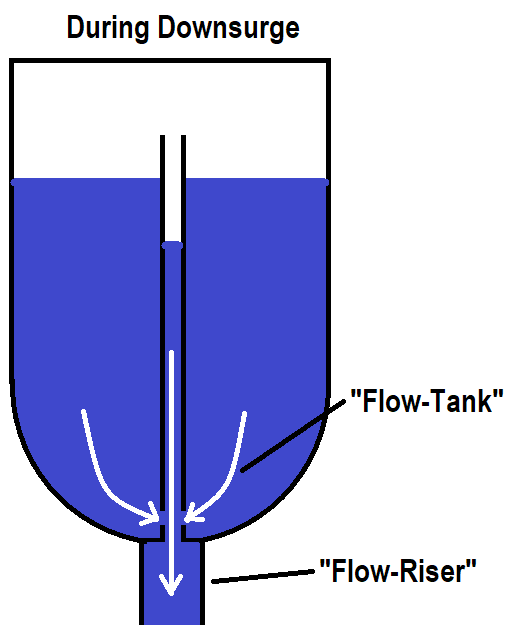
During a downsurge when water starts to leave the differential surge tank, water drains out of the riser, but at the same time water leaves the main part of the tank through the orifice. See diagram below.
The surge tank element is considered a boundary condition, so the Method of Characteristics calculations related to wave propagation and reflection do not apply inside the tank itself. Since these elements are assumed to be relatively small, HAMMER assumes that these effects and any resistance/friction from the riser pipe wall are neglected for a transient analysis. If you expect the friction/resistance from a long length of riser pipe will have an effect on the transient response, I would recommend explicitly modeling that as a pipe element.
When looking at the Detailed text report for extended results for a differential surge tank, the following columns are present:
- Level: represents the water surface elevation inside the main part of the tank. (left and right side of the below diagrams)
- Head: represents the hydraulic grade line in the riser part of the tank (middle part of the below diagrams)
- Flow-Riser: rate of flow into the surge tank riser, which is equal to the flow into the tank inlet. A negative value indicates outflow.
- Flow-Tank: rate of flow into the main part of the tank, through the orifice and the riser top. A negative value indicates outflow.
Surge Tank Properties
The following is a description of the properties of the surge tank element.
Operating Range
- Operating Range Type - choose "level" to enter the minimum, initial and maximum as levels above the base elevation, or "elevation" to enter the actual elevations.
- Note: as of version 10.03.02.75 there is a known issue when using Level where the hidden elevation values will be used instead. It is recommended that you use Elevations.
- Elevation (Base) - this represents the datum elevation that levels are entered in reference to, when the Operating Range Type is set to Level. Often this is set equal to the Elevation (Minimum).
- Elevation/Level (Minimum) - this represents the physical bottom of the tank, below which an air pocket would form. See more here: What happens when a tank becomes empty or full?
- Elevation/Level (Initial) - this represents the starting water surface elevation in the tank. Not used when "treat as junction" is set to True (see calculated "Hydraulic Grade" in the "Results" section, instead)
- Elevation/Level (Maximum) - this represents the physical top of the tank, above which overflow will occur. See more here: What happens when a tank becomes empty or full?
- Use High/Low Alarm - Not used during the transient simulation (see note further below)
Physical
- Elevation - this represents the datum elevation that calculated pressure results will be based on. In most cases it would be considered ground elevation and set equal to the tank bottom elevation if that is where you want pressure to be measured from. For an elevated tank, ground elevation will be lower than the actual tank bottom. If you use actual pipe elevation for your junctions so as to measure pressure from the pipe itself, consider setting this elevation field to the elevation of the
- Section - used to select the cross sectional shape of the tank
- Treat as junction? - this specifies whether the initial hydraulic grade of the tank is based on the Elevation (initial) (set to "False"), or if the HGL is computed for you. See more further below.
Transient (Reporting)
- Report Period - enter a number here to represent how often extended text results will be reported. See "Reporting" further below.
Transient
- Surge Tank Type - Choose either Simple or Differential. A Differential surge tank is a specialized surge tank within a larger tank which provides a fast response. If set to differential, there are several more input values. (see section above). "Simple" is used to model a "normal" surge tank with an inlet opening and open top.
- Has Check Valve - If set to "true", the tank becomes a one way surge tank and liquid cannot enter the tank from the system. In this case, the tank is treated as a junction when running steady state (computing initial conditions.) See more below under "surge tank operation". Note that it is recommended that you use "Elevation" as the Operating Range type in this case (see note further below).
- Weir Coefficient - Coefficient 'k' in the formula for weir overflow, when the water surface elevation exceeds the top of the tank (the "Elevation (Maximum)" field). It is computed as follows: Q = k H^1.5 (H >= 0) where Q is the rate of overflow and H is the height above the top of the tank. The coefficient must be positive. By default, it is a large positive number. For a broad-crested weir, in SI units k = 1.84 L, where L is the width of the weir (refer to Streeter and Wylie, pg 358.)
- Weir Length - The length associated with the overflow weir as described above. Normally it is the perimeter of the top of the tank. Not available when using the "variable" type.
- Diameter (Orifice) - diameter of tank inlet orifice. (or the equivalent circular diameter, if the opening shape is not circular)
- Ratio of Losses - This is the ratio of inflow to outflow headloss and is used to model a differential orifice (see more below). For flows into the tank (inflows), the "minor loss coefficient" is multiplied by this value and the losses are computed using that. For flows out of the tank, HAMMER only uses the "Minor Loss coefficient". So, if you enter a minor loss coefficient of 1.5 and a ratio of losses of 2.5, the headloss coefficient used when the tank is filling would be 1.5 X 2.5 = 3.75.
- Headloss Coefficient - this is used to compute headloss through the surge tank inlet orifice, based on the standard headloss equation (K = V^2/2g). The headloss coefficient applies directly for tank outflows. For tank inflows, it is multiplied by the "ratio of losses" and the resulting coefficient is used. The effect of a differential orifice can be large for some systems.
Note: you may consider adjusting the minor loss coefficient to represent multiple losses through the tank assembly. For example you may have minor losses from bends, fittings, the tank inlet itself and the differential orifice assembly. In this case, you can set the "minor loss coefficient" value to represent all those losses, but remember that the velocity used to calculate them is based on the area of the "diameter (orifice)". Also, you'll need to set up the ratio of losses such that the losses through the entire tank assembly appropriately accounts for the additional loss through the bypass of the differential orifice
Surge Tank Placement / Location
A surge tank is often installed near devices such as pumps and turbines, to keep the water column moving upon pump shutdown.
If the surge tank location is uncertain, you can compute the transient simulation without any protection and check your results (such as the min/max pressure envelope in the Transient Results Viewer.) By viewing these results, you can see critical areas of the pipeline and potentially find a good location for the surge tank(s). You can then add your surge tank(s), re-compute the transient simulation, re-check the results and make adjustments as necessary.
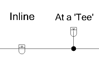
The pipe connecting from the main pipeline to the surge tank can be modeled in HAMMER either implicitly or explicitly. Basically, when laying out the surge tank, it can be modeled at a 'Tee' by laying out the connecting pipe, or can be modeled directly on the main line. When modeling on the main line (the typical approach), the influence of the short piping between the main and the tank can be represented by means of the tank inlet diameter and minor loss coefficient fields. (see more on those further below)
Although explicitly entering the short connecting pipes to the vessel is not incorrect in principle, it may lead to excessive adjustments in pipe length or wave speed which in turn may have an impact on the results. This adjustment commonly occurs with short pipes, due to the fact that HAMMER must have a wave able to travel from one end of the pipe to the other end in even multiples of the time step. So, since you can model the connecting pipe head losses via the minor loss coefficient field, it is often best to model the tank inline. However, you must also consider the effects of water momentum. For example if you're modeling large flows and large diameter pipes, the effects of accelerating that relatively large volume of water (in the connecting pipe) upon emergency pump shut down may be significant.
Differential Orifice
(not to be confused with the differential surge tank type described further above)
The piping connection between the surge tank and the system should be sized to provide adequate hydraulic capacity when the tank is discharging, as well as to cause a head loss sufficient to dissipate transient energy and prevent the tank from filling too quickly. Both of these requirements are met through the use of a piping bypass.
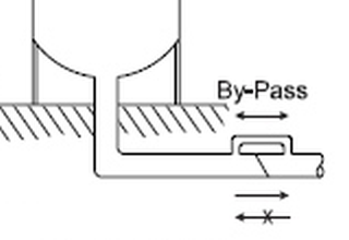
In HAMMER, the headlosses associated with this can be modeled by using the "Minor Loss Coefficient", "Ratio Of Losses" and "Diameter (Tank Inlet Orifice)" attributes of the surge tank. This is referred to as the differential orifice, because the ratio of losses allows you to have the inflow headlosses different from the outflow headlosses. In the above illustration, you can see that the check valve causes inflows to undergo larger headlosses as water passes through the bypass. So, the ratio of losses attribute is usually larger than 1.0 and applies to inflows.
Surge Tank Operation
The surge tank operation depends on how the surge tank is setup in the model. If it is a simple one-way type surge tank, the hydraulic grade observed would initially be above the tank water level as a one-way surge tank's check valve would close to only allow fluid / water to flow out during a low-pressure event to avoid water column separation. If the hydraulic grade during the transient simulation falls below the initial water surface elevation, the check valve opens and water exits the surge tank and enters the pipeline (to keep the water column moving during a "downsurge" transient).
In the case of a two-way surge tank, the hydraulic grade in the pipeline would be more or less the same as the tank hydraulic grade as water is allowed to flow out as well as flow in. When initial conditions are run, the surge tank would behave as a normal tank with level fluctuations as one would observe in an Extended Period Simulation. If your system hydraulic grade is very high at the surge tank location, a two-way tank may not be feasible since it would have to be taller than the hydraulic grade.
A note on "Treat as junction?"
If your surge tank "floats" on the system (hydraulic grade = system HGL, with zero inflow and outflow during normal operations), set the "Treat as Junction?" property to "true". This tells the initial conditions solver to treat the tank as a junction, and therefore calculate the HGL as if there is no tank present. The resulting HGL is then used as the starting water surface elevation of the tank, instead of the "Elevation (initial)". This provides an easier way to model a tank whose HGL floats on the system; otherwise you would need to adjust the "Elevation (initial)" until the tank had zero inflow and outflow, and may need to do so repeatedly for different scenarios and other changes to the model. With this option set to True, ensure that the resulting HGL does not fall below the "Elevation (minimum)" or above the "Elevation (maximum)".
Note: Sometimes the surge tank may fill up or empty too quickly to observe the mitigation of the transients produced. In such times, it is better to set up a higher “report time” and a smaller time-step to observe the tank filling and emptying. Refer this link for more details.
Reporting
Starting with HAMMER CONNECT Edition Update 3 version 10.03.04.05, you can also view results in the Extended Node Data tab in the Transient Results Viewer. This includes surge valve results Level, Inflow, and Spill Rate. See this link for more information: How to view extended node transient results for HAMMER elements. Note: that Extended Node Data results are only available for simple surge tanks.
For versions below 10.03.04.05, surge tank-specific output results are found in the Transient Analysis Detailed Report.
To prepare for viewing this information, first check your transient calculation options. "Show standard output log" and "Enable Text Reports" should be set to "True". Next, enter a number for the "Report Period" field of your surge tank. This represents how often extended text results will be reported. For example, if your time step is 0.01 seconds and you enter '10' for the report period, it means you'll see extended results every 10 time steps or every 0.1 seconds.
Other extended results, such as for differential surge tanks, are also available in the Transient Analysis Detailed Report. This is found under Report > Transient Analysis Reports. Scroll down near the bottom, to the section starting with " ** Surge tank at node" and you will find a table of Level, Head, Inflow and Spill rate.
- Level: represents the water surface elevation inside the surge tank.
- Head: represents the hydraulic grade line in the pipeline just outside of the surge tank inlet.
- Inflow: rate of flow into the surge tank. A negative value indicates outflow.
- Spill-rate: the rate of flow that spills over the top of the tank, per the weir equation.
- Flow-Riser (for differential surge tanks): rate of flow into the surge tank riser, which is equal to the flow into the tank inlet. A negative value indicates outflow.
- Flow-Tank (for differential surge tanks): rate of flow into the main part of the tank, through the orifice and the riser top. A negative value indicates outflow.
Note: if high and low alarms are setup to trigger when violated the same would be reported when the initial conditions are run. However, these would not be reported when Transient Analysis is performed. Refer this article for more details.
Surge Tank Overflow
When the surge tank Section type is set to Circular or non-circular, the Weir Length and Weir Coefficient fields are exposed and are used to calculate the overflow rate for a given headwater above the tank top. A summary of the total overflow volume is displayed as a User Notification. Starting in version 10.03.04.05, you can view spill rate results for simple surge tanks in the Extended Node Data tab. This can also be found in the Transient Analysis Detailed Report. If you have a differential surge tank or an older version of HAMMER, you would need to use this report to view spill rate results.
When the surge tank Section type is set to Variable, the Weir Length and Weir Coefficient fields are not available and not used. Instead, when the water surface elevation exceeds the top elevation of the cross section curve, the total inflow into the tank is treated as overflow. In other words when the tank is full, all flow into the tank becomes overflow and the actual weir head/flow change is not accounted for.
One possible workaround for this (if you have a varying-area tank and need to account for overflow based on the actual overflow/spillway elevation) is to model two separate tanks, one with the traditional circular/non-circular section type in order to model the weir overflow, and another set to the variable area type, to model the excess area from the parts that vary. The regular section tank area would be deducted from the variable section area. Both tanks would have the same base elevation and you could connect them with a short, smooth, large diameter pipe. See related forum discuss here.
Surge Tank Inflow
In some cases your surge tank may be at the upstream-most point in the network and may receive inflow from the top.
In the properties of the surge tank (and regular tank element) you will see the "demand collection" fields where you can enter a positive value for the demand to model flow leaving the tank, or a negative value for the demand to model an inflow. However, if you need to model a specific inflow entering the top of the tank, please be aware that currently this is not supported during the transient simulation (reference number 1329593).
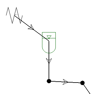
Instead, to model the tank inflow during the transient simulation, you could add an extra pipe upstream of the surge tank node, connected to an upstream Periodic Head-flow element. The Periodic Head-flow would be configured with an inflow pattern (negative values for the flow). You may need to adjust the tank orifice diameter and/or ratio of losses field since the inflow from this new upstream pipe would technically enter through the inlet orifice. (see more on those fields further above)
Also, if you want to assume a constant water level / hydraulic grade for the water source for your hydropower system, consider using a single reservoir node instead of the tank, with the elevation set to the assumed fixed elevation. If you need to assess the balance of inflow vs. outflow (and resulting change in water level) in the surge tank during a transient simulation, you would need to use the tank or surge tank element as described above.
Troubleshooting
"Invalid tank Operating Range"
If you encounter a red user notification indicating that the tank operating range is invalid, check to make sure that the "initial" is between the "minimum" and the "maximum" field in the "Operating Range" section of the properties. If the "operating range type" is set to "level", note that the minimum, initial and maximum values represent distances above the "base" elevation.
"The initial water elevation cannot be zero for a surge tank that has a check valve."
If you encounter this red notification, check the surge tank's operating range. Ensure that the initial level or elevation is between (and not equal to) the minimum and the maximum. If using a check valve (one way surge tank), the calculated hydraulic grade (seen in the "Results" section of the properties) is used for the initial HGL< which can be above the initial and maximum water surface elevation.
If everything appears to be set correctly and you are using Level as the Operating Range Type, try switching it to "Elevation", enter appropriate/equivalent elevation values, then switch back to Level. This is caused by a known issue as of version 10.03.02.75 which will be resolved in a future version (reference #535850)
Reported Levels in Transient Output Log are not correct based on the operating range input
This is related to the issue above - as of version 10.03.02.75 there is a known issue when using Level where the hidden elevation values will be used instead. It is recommended that you use Elevations.
Transient results are unstable or rapid oscillation is seen
First, ensure that you do not have multiple surge tanks that are hydraulically close as this can cause instability due to the quick changes that can occur. Consider combining tanks and simplifying with conservative assumptions made where necessary. If you are using the "chimney" approach mentioned in this article to model surcharging of an enclosed surge tank, this can also lead to instability due to the fast changes in HGL that can happen with relatively small changes in volume. Consider also using a smaller transient timestep to capture such fast changes.
See Also
Hydraulic grade above top of one way surge tank
How can I see the amount of inflow or outflow occuring for a particular surge tank during the transient simulation in HAMMER?
What happens when a tank becomes empty or full?
How can I model a Vent Pipe or Stand Pipe in HAMMER?
Using the Ratio of Losses field for hydropneumatic tanks and surge tanks
Determining the Headloss Coefficient for a hydropneumatic tank or surge tank