| Product(s): |
SewerGEMS, SewerCAD |
| Version(s): |
10.XX.XX.XX, 08.11.XX.XX |
| Area: |
Modeling |
Problem
When running an Extended Period Simulation for gravity flow, the flow variation in the conduit doesn’t follow the loading pattern specified.
Background
This can happen for a model containing the following;
- The model contains a number of Property Connections connecting to conduits via taps and laterals
- The Property Connection is specified with a sanitary base flow and a pattern to govern the flow
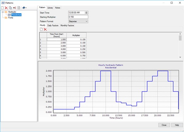
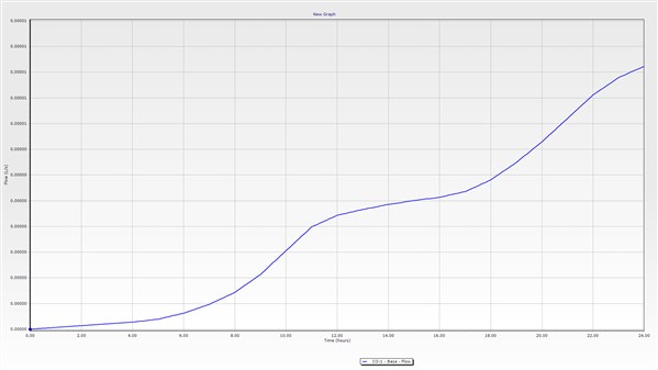
When the model is analyzed using the GVF-Convex Solver, the flow variation in the conduit does not reflect the loading pattern specified at the Property Connections. The pattern is visible in the lateral element connecting the property connection to the conduit. For example, the flow pattern specified at the property connection would look like this when the lateral element is graphed;
This flow follows the loading pattern specified at the property connection which looks like this;
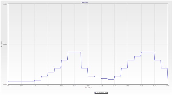
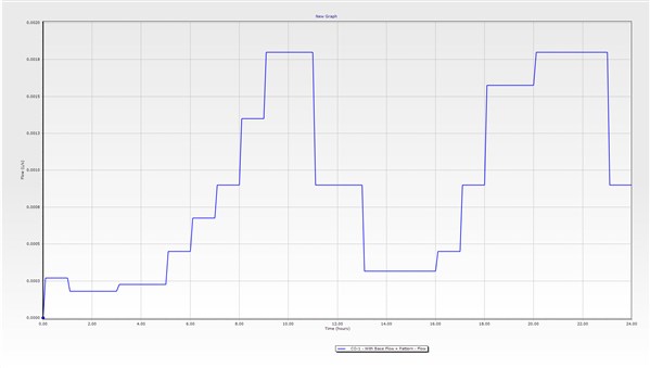
However, when the conduit to which the property connections are connecting is graphed, the flow variation would look like this;
The graph above shows that flow is steadily increasing and continues to increase which shows that the pattern specified is not visible in the flow fluctuations in the conduit.
Solution
This unrealistic flow attenuation can be caused by very low base flow values (order of 0.0001 L/s) specified at the property connections resulting in the convex routing factor “C” to be of a small value. The convex routing factor “C” is used in Extended Period Analysis with the GVF-Convex Solver. It depends on the representative flow and length of the conduit. Since, the flow is very low contributing from all the Property Connections the convex routing factor value computed by the software is very low. This is resulting in unrealistic attenuation of flow. The graph for the conduit is showing a steady increase in flow over time and not following the flow pattern in which flow is included in the conduit by the Property Connections.
The convex routing factor can be found in the Calculation Options of the GVF-Convex Solver under Convex Routing;
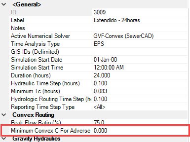
The default value is kept at “0” (zero). However, a convex routing C factor from 0.3 to 1 would yield realistic results in such cases. When a factor of 1 is used for the convex routing C factor, a more realistic flow variation can be seen in the conduit;
Note that if you are seeing a complete lack of flow being accounted for from one or more inflows, this could be due to a known issue related to the orientation of the pipe. You may notice that the "start node" in the conduit properties is actually set to the downstream element. If you use the reverse option to change the orientation, the problem should no longer occur.
See Also
Conduit flow increases as you move downstream, with no additional inflow
Flow Attenuation - Why does flow or velocity sometimes decrease when moving downstream?