| |
Product(s): |
StormCAD |
|
| |
Version(s): |
10.02.00.55 |
|
| |
Area: |
Installation |
|
Overview
The CONNECT Edition Update 2 release of StormCAD introduces numerous improvements and features to help you be more successful. Let's explore each of these in detail.
Table of Contents
CONNECT Licensing
This release uses CONNECT Licensing, a major advancement in Bentley's product licensing methodology. CONNECT Licensing gives organizations much more control over license usage and reporting, with the capability to establish concurrent use thresholds, groups of users with different levels of access and more. Selecting the StormCAD license feature level (number of inlets, and whether or not you can integrate with AutoCAD) is also much more clear to the end user. More information on CONNECT Licensing and how it works can be found here: Licensing OpenFlows | Hydraulics and Hydrology Products - CONNECT Licensing
Important note: with CONNECT Licensing, you will need to sign in to the CONNECTION Client (included with installation of StormCAD). If you do not currently have an account that is properly linked to your organization, please contact your Site Administrator, who can add you.
Compatible Operating Systems and Platforms
Compatible Operating Systems
Windows 10 (32-bit or 64-bit)
Windows 8 (32-bit or 64-bit)
Windows 7 (32-bit or 64-bit)
Compatible Platforms
The Standalone version does not require any CAD or GIS software to work. However, it can be integrated with the following platforms:
MicroStation V8i SELECTseries 4 (Some earlier versions may work as well. MicroStation CONNECT Edition integration is not yet supported with this release.)
AutoCAD 2019 or 2018
StormCAD is now compatible with ProjectWise build 10.00.02.320
See: Platform Compatibility
Change Tracking
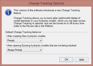
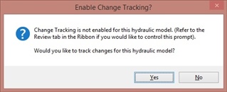
Change Tracking enables you to keep track of and review changes made to your hydraulic model, including who made the change and when it was made. If multiple users work on the model, this can provide a helpful audit trail so you can determine who made a certain change and when. When you open a new or existing model, you will be asked if you want to track changes in the model.
Once you make changes to the model and save it, you can review elements that have changed since the last time by going to Review tab and select Change Tracking > View Tracked Changes. If you have a lot of items in the table, you can filter this by clicking the Filter button at the top of the table.
Network Connectivity Reviewer
The Network Connectivity Reviewer enables you to quickly check for common connectivity issues that may arise when building a model, speeding up the overall model building process.
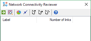
This tool is accessed by going to Tools > Tools > More > Network Connectivity Reviewer or searching for this in the Ribbon Search feature. The Network Connectivity Review enables you to verify the number of subnetworks in the model, check the direction that the pipes are laid out in, and check the connected elements upstream and downstream of a node.
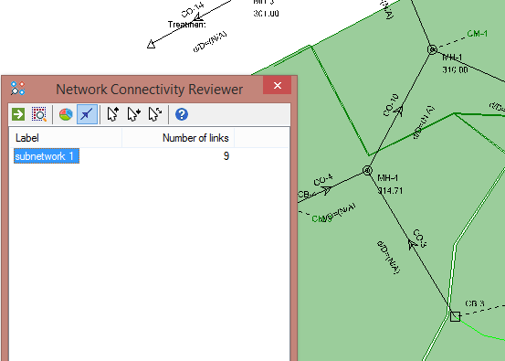
Click the Generate Subnetworks button in the upper left to start. You can highlight these, which will quickly allow you see the location of possible system disconnections.
You can also check and display the pipe direction by clicking the “Show pipe direction…” button. If there are no results stored for the model, this will show the direction of the pipe from start node to stop node, as shown in the screenshot below. This can help in cases where the pipe orientation may be a problem that you want to correct.
Using the “Trace upstream…” and “Trace downstream…” buttons, you can select an element on the drawing and to see if the elements are either downstream or upstream of the element. There is also a “Find connected…” button that will enable you see all elements connected to a selected element.
Gutter Cross Section Viewer
You can now generate and use a gutter cross section based on a terrain model, and view the gutter cross section along with water depth results. This enables you to establish your gutter cross sections much faster, using your existing terrain data, and enables better visualization of the depth and spread.
The Gutter Cross Section Viewer is accessed through the gutter properties by selecting the ellipsis button (…) in the Gutter Sections property field.
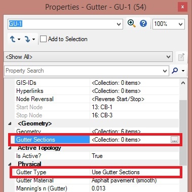
The program will use gutter sections if you select “Use Gutter Sections” for the Gutter Type. You add gutter cross sections using a terrain model. You can build the gutter cross sections from both the Terrain Model manager and from the Gutter Sections collection field in the element properties.


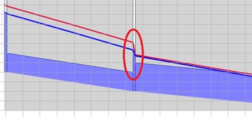
Once the gutter cross section is built, you can view a schematic of the gutter cross section by opening the Gutter Sections collection field. If you compute the model, the schematic will show the hydraulic grade. If applicable, you will be able to scroll through time to see how the hydraulic grade in the gutter changes with time. In addition, the lower part of the Gutter Section dialog shows numerical results.

Calculation Updates
Entry/exit losses for culverts in GVF solvers
Previous versions did not account for entry and exit losses in a culvert. With this version of StormCAD, these losses are now accounted for, as shown in the screenshot below.
Improved results when using Partial Area Effects
When the “Correct for Partial Area Effects?” option is set to True, if there are two or more Rational flows entering a single node, the solver will use the system time that produces the largest Rational flow. This release sees improved results when using this method.
Other Features
Additional source file support for Terrain model tool
DXF point files, Contours, and ESRI Shapefiles are now supported in the Terrain Model tool.
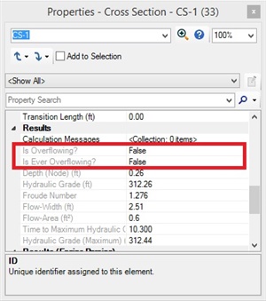
“Is Flooded?” and “Is Ever Flooded?” for cross-sections
New property fields for “Is Flooded?” and “Is Ever Flooded?” have been included for cross section element, which will enable you to quickly tell if the start and stop of a channel will overflow at a given time step or at any point during the model run.
“Same as Stop Node” option for Gutter Types
“Same as Stop Node” option is now included for the gutter property Gutter Type, providing a quicker way for you to define gutter properties. When this is selected, the gutter will use the input entered for the catch basin on the gutter’s stop node. This setting can only be used if the stop node is a catch basin. If the stop node for a gutter is an outfall, a user notification will be generated indicating that the Gutter Type is not valid.

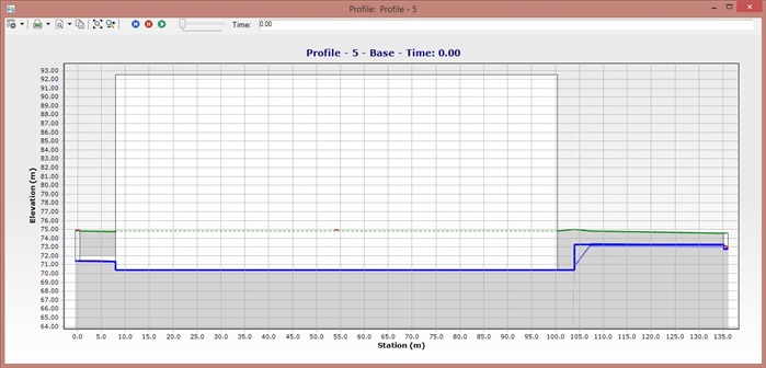
Profile Visualization of Storage Chamber System
Profiles of storage chamber systems will now accurately display the dimensions, for better profile visualization. This is seen for pond elements whose Volume Type is set to “Storage Chamber System”, with a storage chamber assigned to it.
Updated workflow for Trace Upstream, Trace Downstream, and Shortest Path queries
The queries for Trace Upstream, Trace Downstream, and Shortest Path have been streamlined to make it both easier and quicker to use.
Sorting based on Labels for FlexTables when generating Custom Report
FlexTables added to a Custom Report can be sorted by label, enabling the user to better display the elements in a report.
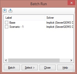
Updated workflow for selection of scenarios in Batch dialog
A new import and export feature has been included in the Batch dialog. You can select a set of scenarios in a batch and export these selections out to a Scenario Batch Run (.sbr) file. If you clear the batch selection, you can then quickly select them again by importing the Scenario Batch Run file again. This can be particularly useful for models with a large number of scenarios, to enable you to switch between different batch runs quickly.
Ability to apply Terrain Model elevation data to selected nodes
Previously, the Terrain Model feature would only apply elevations to newly created elements, or elements that were moved. To make it easier to update all (or a selection of) model element elevations, a new option has been added to Apply Ground Elevation to Selected Nodes.
To use this, select the desired elements (or use CTRL+A to select all elements), then right-click on an active terrain model in the Terrain Model manager and select “Apply Ground Elevation to Selected Nodes.” Any selected nodes within the boundaries of the terrain model will have its ground elevation updated if the option “Update Ground Elevation from Terrain Model?” is set to true.
StormCAD TechNotes and FAQs
Downloading OpenFlows | Hydraulics and Hydrology Software
Software installation order
Cumulative patch set information
Set up notifications for new versions and patch set releases

| |
Original Author: |
Scott Kampa |
|