| Product(s): |
HAMMER |
| Version(s): |
CONNECT Edition, V8i |
| Area: |
Layout and Data Input |
Problem
For a pump or turbine, there is a limited set of default "Specific Speed" options available. How can I add my own specific speed for a pump or turbine, to model a custom quadrant characteristic curve to use during a transient simulation?
Background
During the initial conditions calculation (steady state), HAMMER uses a pump's pump definition to determine the initial operating point of the pump, and the Turbine Curve to determine the initial operating point of a turbine. However, during a transient simulation HAMMER uses a special characteristic curve to represent the behavior of a pump or turbine, based on the "specific speed" selection (in the "transient" tab of the pump definition, or the properties of a turbine). The specific speed determines which four-quadrant curve to use, which defines the shape of the curve that can operate in all four quadrant (not just positive head/flow/speed). HAMMER applies the pump/turbine initial operating point to this curve's "shape", to construct the actual curve used during the transient simulation.
The formula in the link below can be used to estimate you pump or turbine's specific speed, and you can select the closest available default specific speed. The source of the default specific speeds (quadrant curves), is explained in another link found below.
Solution
Although the closest default specific speed is often adequate, your own, custom four-quadrant characteristic curve for your pump or turbine can be added in a special text file. This is located in the HAMMER installation folder, and is named QuadrantCurves.txt
Note that there are two versions of this file - one used by the 32-bit version of HAMMER (and in HAMMER for MicroStation and HAMMER for ArcMap) and the other for the 64-bit version (this is the default for the Standalone version of HAMMER, and if you use HAMMER for AutoCAD 64-bit). Ensure that you add your custom curve to both. See more here: Custom quadrant curve not being recognized
The default specific speeds are defined in the file QuadrantCurvesPredefined.txt - this file should not be edited, but could be used as an example to understand the format required for your custom characteristic curve.
Note: in versions 10.01.01.04 and earlier, upgrading to a new version would result in the quadrantcurves.txt file being removed and replaced with the default blank file (losing any changes). This has been resolved starting with version 10.02.00.43 (reference # 764788) - when installing this version (or newer), any existing quadrantcurves.txt file in your previous HAMMER installation will be retained. Be sure to install the newer version to the same folder as the previous.
Comprehensive details on adding your custom four-quadrant curve can be found in the HAMMER Help documentation, in the topic Creating Models > Elements and Element Attributes > "Pump and Turbine Characteristics in HAMMER"
Pumps
Pump specific speeds are defined under the [PUMPS] section. There are several different formats that can be defined, primarily Circular and Suter. Note: Pump data can be specified in one of the following formats: Circular format, Suter format, Suter Thorley format, or Suter Chaudhry format. More details for the different formats can be found in the Help documentation under the topic "Pump and Turbine Characteristics in HAMMER."
Circular format
For the Circular format, the relative values of Q (flow) and N (speed) along lines of 100% head (QH and NH) and 100% torque (QM and NM) are entered at a suitable interval throughout the entire operating range of the pump:
SPECIFIC SPEED (US/SI): [Specific speed, US units] /
[Specific speed, SI units]
CURVE FORMAT: CircularFormat
HEAD: NHD
QH,1 NH,1
QH,2 NH,2
. .
. .
QHNHD NH,NHD
TORQUE: NMD
QM,1 NM,1
QM,2 NM,2
. .
. .
QM,NMD NM,NMD
Where NHD and NMD are the number of head and torque data points respectively.
The discharges and speeds are given in percent (%) and are relative to the pump's rated discharge and speed (based on the initial conditions flow and speed). The specific speed must be entered as an integer value so that it can be correctly parsed to appear in the HAMMER user interface. Also note that large positive and negative Flow, Speed pairs are recommended in order to properly describe the asymptotes of the 4 quadrant curves.
Suter format
For the Suter format (described in Fluid Transients (Wylie & Streeter, 1978)), pump characteristic data is presented in terms of two angular functions, WH(x) and WB(x) which are determined using the
following relations:
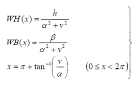
Where h, v, β, α are respectively the non-dimensional head, discharge, torque and speed normalized by the rated head, discharge, torque and speed. The data file format is as follows:
SPECIFIC SPEED (US/SI): [Specific speed, US units] /
[Specific speed, SI units]
CURVE FORMAT: SuterFormat
HEAD: NHD
x1 WH1
x2 WH2
. .
. .
xNHD WHNHD
TORQUE: NMD
x1 WB1
x2 WB2
. .
. .
xNMD WBNMD
Where NHD and NMD are the number of head and torque data points respectively.
Note that in order to provide satisfactory calculation results, it is important to describe points where the sign of the WH(x) and WB(x) functions changes from positive to negative and vice versa. However, due to internal translations in the HAMMER engine, WH(x) and WB(x) can approach, but should never equal, zero (minimum values of 0.0001 are suggested for both functions).
More details on the different formats (Suter, Suter Thorley, or Suter Chaudhry) are documented in the aforementioned Help topic.
Turbines
Turbine specific speeds are defined under the [TURBINES] section. The format is similar to the pump "Circular" format, but there is a characteristic curve for each position of the wicket gate. So, it is often difficult to find enough information to construct a custom turbine characteristic curve in HAMMER. It is recommended that you use this equation to estimate the turbine specific speed and select the closest available default Specific Speed. Consider a sensitivity analysis, trying a few nearby Specific Speeds and testing if they have a notable impact on the transient results.
Note that currently Turbines in HAMMER are always expected to operate in the first quadrant of operation (positive flow and positive speed).
SPECIFIC SPEED (US/SI): [Specific speed, US units] /
[Specific speed, SI units]
NUMGATES: NG
GATE: WG1 ND1
H1,1 Q1,1 P1,1
H1,2 Q1,2 P1,2
. . .
. . .
H1,ND1 Q1,ND1 P1,ND1
. . .
. . .
GATE: WGNG NDNG
HNG,1 QNG,1 PNG,1
HNG,2 QNG,2 PNG,2
. . .
. . .
HNG,NDNG QNG,NDNG PNG,NDNG
Where NG represents the number of different wicket gate opening percentage positions described in the data; WGi represents a particular gate opening percentage value; ND is the number of data points for the associated gate opening value; H, Q and P represent head, flow and power respectively (the first subscript of H, Q and P denotes wicket gate position index, while the second one is the data index for that wicket gate position);
It should be noted that:
(a) WGi, Hi,j , Qi,j and Pi,j are in percent (%) relative to rated head, flow and power (H, Q and P), or full gate opening (WG)
(b) WGi increases with i.
(c) Hi,j , Qi,j and Pi,j decrease with j, for fixed i.
(d) WGi should be between 20% and 100% (inclusive). Below 20% gate opening, HAMMER currently assumes a linear decrease in flow until the time the gate opening equals 0%. See: Why do turbine extended transient results stop at the time when the gate is 20% open?
What if I have triplets (N11, Q11, M11) of speed, discharge, and torque for my turbine, and need to convert to HAMMER's expected triplets (H%, Q%, P%) of percentage values of head, discharge, and power?
You can use these equations to help calculate the required data. Note, the rated data for the full-scale turbine, with diameter D (m), are denoted below by the subscript R.
First, find the rated values NR (rpm) and HR (m) for your turbine, along with the unit values N11R, Q11R and M11R.
Solving the unit formulae for head (H), flow (Q), and torque (M), you obtain:
H = D2 (N / N11 )2 (m)
Q = D3 Q11 N / N11 (m3 /s)
M = D5 M11 (N / N11)2 (N m)
Which can be used to calculate QR and MR
Then, the rated output power PR and efficiency ηR are estimated as:
PR = (p / 30) NR MR (W)
ηR = PR / (10-3 ρ g QR HR) - where ρ is fluid density and g is acceleration due to gravity
while the specific speed, NS, of the unit is:
NS = NR PR0.5 / HR1.25 (kW0.5 /m1.25)
Finally, for constant speed:
H% = 100 H / HR = 100 (N11R / N11)2
Q% = 100 Q / QR = 100 Q11 N11R / (Q11R N11)
P% = M% =100 M / MR = 100 M11 N11R2/ (M11R N112)
The unit formulae are generally applicable. To work out, say, QR you need to use Q11R, NR and N11R
See Also
Estimating the Specific Speed of a Pump or Turbine
Source of the default Specific Speed for pumps and turbines
Custom quadrant curve not being recognized
How to add comments on custom pump and turbine quadrant curves