| Product(s): |
SewerGEMS, CivilStorm |
| Version(s): |
V8i, CONNECT Edition |
| Area: |
Modeling |
Problem
How to I model a flap gate (check valve or "tidal gate" that prevents reverse flow) and how do I account for the head (pressure) needed to reopen a closed flap gate? For example a "duck bill".
Background
A tidal gate can be modeled by choosing "True" for "Tidal gate?" in the properties of the outfall node element, along with the Implicit or Explicit (SWMM) numerical solver (selected in the calculation options).
You can also select "true" for "Flap Gate?" in the properties of a conduit, to model a check valve that only allows flow through in one direction, based on the orientation of the pipe (see the Start Node and Stop Node at the top of the properties window).
Note that even if you see zero flow through a flap gate, the hydraulic grade can still rise (for example you may see the pipe fill in profile view) if the hydraulic grade is influenced by other connected elements. For example a user defined tailwater at a downstream outfall - upon positive flow, the hydraulic grade can be "communicated" to and influence the water level at the upstream flap gate.
The flap gate feature does not model headloss that may occur through the flap gate, or the head required to open a closed flap gate. Below are two possible approaches for modeling headloss through the gate itself. In some cases it can take a certain amount of head (pressure) to open the closed flap gate.
Solution - conduit control structure (Explicit solver)
When using the Explicit (SWMM) solver, consider using a user defined tailwater on the outfall in conjunction with a depth-flow conduit control structure to model the headloss.
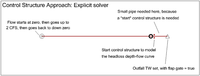
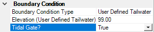
To model the downstream water level, choose "User defined tailwater" for the "boundary condition type", then enter the tailwater.
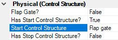
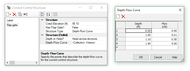
To account for headloss through the gate itself (for example a "duck bill"), use a Start Control Structure on the upstream conduit, using a Depth-Flow table. Insert a transition element right near the end of the conduit adjacent to the outfall, so you are left with a short pipe right near the outfall, which you can use to place your start control structure.
Note:
- Stop control structures are currently not supported for outfalls, so you will need to use it as a Start control structure (hence the need for the short pipe next to the outfall).
- Be sure to enter a "crest elevation" in the control structure, representing the bottom of the upstream end of the pipe adjacent to the outfall.
- Be sure to add a small slope to the final, short pipe, and make sure it is not too short as that can sometimes can stability problems. For example a 10 foot long pipe with a drop of 0.1 ft between the upstream and downstream invert.
- Choose "Head across structure" for the "depth or head" option, then enter depths (not elevations) in the Depth-Flow curve table
- You may need to select "true" for the calculation option "Use Bentley Transition Equation", with a small Routing Step, if the results are not stable.
Solution - Elevation-Flow curve (Implicit solver)
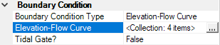
Another possible approach, suitable for the Implicit solver, would be to model it with an elevation-flow curve on the outfall. For the Boundary Condition Type, choose Elevation-Flow Curve, keep the "Tidal gate?" set to "false" (it will be modeled by way of the elev-flow table), then enter the table of Elevation and Flow to simulate the upstream headwater elevation that would occur for a given flow through it.

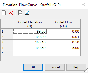
This can simulate the initial head needed to open a closed tidal gate by entering a zero flow for hydraulic grades below that which would open it. For example if an outfall is at an invert elevation of 99 ft and it takes 1 ft of head to "push" the closed tidal gate open, you could enter zero flow at an elevation of 99 ft and a tiny flow at an elevation of 100 ft (99+1).
If you have a table of flow vs. headloss from the manufacturer of the flap gate, you can enter that by determining the tailwater elevation that would occur for a given flow. For example if your outfall has an invert of 99 ft and you have a point on the head vs. flow curve that states you have 0.5 ft of headloss at a flow of 5 ft^3/s, then you would enter a row in the outfall Elevation-Flow Curve with 99.5 ft (99+0.5) for the "Outlet Elevation" at a flow of 5 ft^3/s.
Your table may look something like this:
Numerical Stability
If you encounter numerical instability or results that do not appear to be correct, try using a different solver/approach, or adjust the advanced calculation options. A smaller timestep or routing step may help in this case. See more:
Troubleshooting unstable SewerGEMS and CivilStorm results using the implicit solver
Troubleshooting unstable SewerGEMS and CivilStorm model results using the Explicit SWMM Solver
Example Model
Here is an example model, which can be opened in version 10.01.01.04 and greater. You must be signed in to download.
Flap gate headloss example
See Also
Conduit start/stop control structures