| Product(s): |
SewerGEMS, CivilStorm, StormCAD, SewerCAD |
| Version(s): |
10.02.xx.xx and later |
| Area: |
Modeling |
Introduction
This article explains how to use the Gutter Cross Section Viewer tool to visualize and view gutter results. This feature is available in CONNECT Edition Update 2 and greater (10.02.XX.XX + )
Note: You can also visualize results at cross section elements. See this article for details on the same: Visualizing results for cross section elements
Importing data through terrain models
When you are using a terrain model, you can create gutter cross sections and view the gutter cross section along with gutter depth and spread results. This enables you to establish your gutter cross sections much faster, using your existing terrain data, and enables better visualization of the depth and spread. Note: the Gutter Type in the gutter properties needs to be set to "Use Gutter Sections" to use this feature.
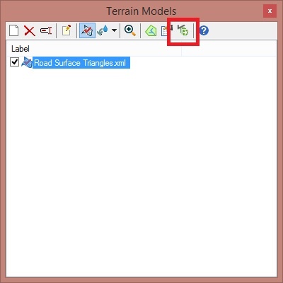
To begin, open the Terrain Model manager from the View tab and add your terrain model. Once you have done this, you can build the gutter sections by clicking the "Batch Build Gutter Cross-Sections from Terrain Model" button. You can also build the gutter sections by opening the gutter properties and clicking the ellipsis button (...) in the Gutter Sections property field.
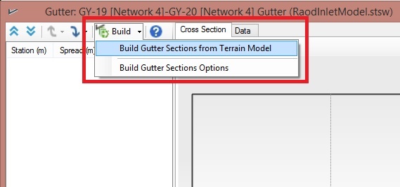
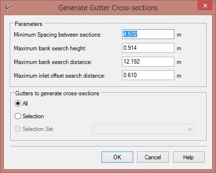
When you built the model, you have access to the gutter cross-sections properties, which enables you to define the spacing of the sections and to define if you want a selection set of gutters to apply.
Viewing Gutter Sections
The Gutter Cross Section Viewer is accessed through the gutter properties by selecting the ellipsis button (…) in the Gutter Sections property field.
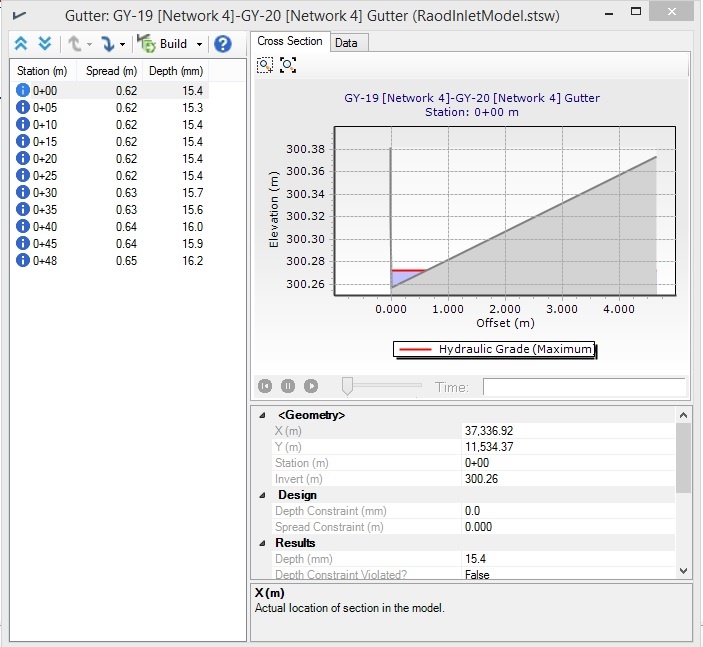
Once the gutter cross section is built, you can view a schematic of the gutter cross section by opening the Gutter Sections collection field. If you compute the model, the schematic will show the gutter depth and spread results at a given time step (for solvers using an EPS run), as well as the maximum depth in the gutter. By clicking the Preview Station or Next Station buttons, you can scroll through the different stations in the gutter, enabling you to see how the spread and depth will change in different parts of the gutter. There is a Move Upstream and Move Downstream buttons that will enable you to move to the next gutter downstream or upstream of the selected element.
If applicable, you will be able to scroll through time to see how the depth in the gutter changes with time. In addition, the lower part of the Gutter Section dialog shows numerical results.
Note: Previous releases reported if one of the HEC-22 gutter section shapes is detected, such as Uniform, Composite, Parabolic, V-shape. Starting with CONNECT Edition Update 3 (version 10.03.03.44), if one of the HEC-22 sections gutter section shapes is detected, the geometry parameters like cross slopes are reported.
For more information, please see the Help documentation.
Visualization of Gutter spread in plan view using civil products
Civil products like OpenRoads Designer, OpenSite Designer utilize OpenFlows Technology for Drainage and Utilities modeling. You can directly import existing Storm water model into ORD.
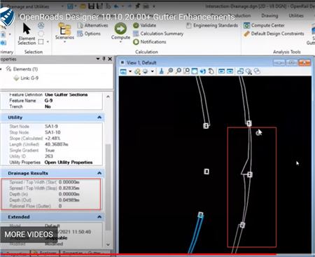
If you have access to civil product e.g. OpenRoads Designer (10.08.00.88+), then under drainage and utilities you can visualize the spread at gutters using Gutter sections in the form of spread polygons. You will need to first define feature definitions for gutters, and then using terrain model as specified above you can generate gutter sections, which will help in showcasing gutter spread results like shown below.
Here are videos to understand how to achieve this in ORD.
(+) Video: Gutter Sections in Drainage and Utilities - OpenRoads | OpenSite Wiki - OpenRoads | OpenSite - Bentley Communities
Video: Gutter Enhancements showing spread widths
See Also
Using Downstream Trace and Digital Terrain Models
Visualizing results for cross section elements
OpenRoads | OpenSite OpenRoads | OpenSite Wiki