| Product(s): |
WaterSight |
| Version(s): |
10.00. |
| Area: |
Documentation |
Overview
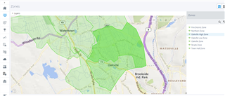
Entering and editing information about zones balances (inflows, outflows and storage sensors) and zones characteristics.
Zones should correspond to isolated areas of the system, surrounded by closed valves and where all inflows and outflows (if exist) must be measured. Zones can include for example DMA (District Metered Areas), pressure zones or operational zones. The configuration of the inflow and outflow sensors as well as tanks levels are done by editing the Flow In, Flow Our and Storage Columns. As an important note, the tank levels that should be considered for the zones balance are only those that are inside the zones boundary and serve as storage for the zone - this means that if a zone is supplied by a tank and the inflow sensor is located immediately downstream the tank (and already considered for the zone balance as input), this tank level must NOT be considered.
Note: System Total zone is always automatically created (this information does not come from GIS shapefile) and represents the all system.
To add more zones, the user needs to upload a new zone shapefile, in the GIS configuration page.
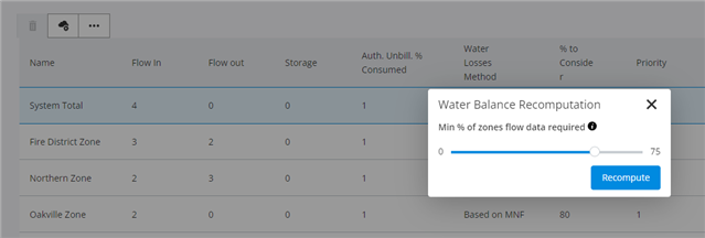
Recompute data 
By clicking on the recompute data above the table, all the zones monthly water balance components will be recalculated again. The user can use this option to define:
- Minimum percentage of zones flow data required to calculate zone system monthly input volume AND/OR
- Recalculate zones water balance components whenever zones parameters presented in the zone admin table are changed/updated
Minimum percentage of zones flow data required to calculate zone system monthly input volume
Zone monthly system input volumes (that will be displayed in the water balance charts) are automatically calculated based on the final zone flow time series, that is a balance between all inflows, outflows and storage sensors into the zone. By default the solution assumes that for each month at least 75% of the time zone flow data needs to exist (this means that in a 30 days period, at least 22 days need to have zone data) otherwise system input volume will not be calculated. However, when clicking in the recompute data, a pop-up dialog will appear and the user can change the 75% default that is assumed, by moving the range slider to the left or to the right.
If the user for example defines a value of 50% this means that system input volume for each zone will be calculated until a maximum of 50% of missing data (for each month). For the period with data, the real zone flow time series will be used for calculate the system input volume. For the other 50% period without data, the software will estimate the monthly volume by assuming, for the missing period, the zone pattern (P50th percentile of the zones flow, considering a historical period of last 1 month).
Recalculate zones water balance components whenever zones parameters are changed/updated
Whenever some zones parameters are edited in the zones admin table below, automatically the new water balance components for the future months will also change based on the new assumptions. For example:
- when changing zones inflow, outflows and/or storage sensors, automatically for the future months the zone system input volume will be calculated according with this new balance;
- when changing authorized unbilled consumption percentage, automatically for the future months the zone authorized unbilled consumption component will be calculated according with this new percentage;
- when changing the water losses method, automatically for the future months the apparent and real losses volumes components will be calculated according with this new percentage.
If the user changes the zones parameters in the admin zones table but does NOT click in the recompute button, the zones changes made will only reflect in the update of the water balances calculation for the future months (not affecting past months). If the user changes the zones parameters in the admin zones table and DOES click in the recompute button, then all the water balance components will be recalculated, including for all the past months.
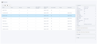
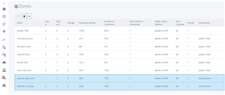
Zones Configuration table
| Column |
Description |
| Name* |
Required field. Zone display name that will appear in the software. This name should be the same used in the shapefiles uploaded in the GIS configuration page. |
| Population served |
Population served by each zone |
| Number of Customers |
Number of customer supplied by each zone |
| Number of Connections |
Number of service connections for each zone |
| Water Losses Method |
Method to use for calculating water losses. The following options are available:
- Real losses calculation based on the zone minimum night flow (MNF)
- Apparent losses (AL) calculation as an user defined percentage of the total zone input volume
- Apparent losses (AL) calculation as an user defined percentage of the total zone revenue volume
- Apparent losses (AL) calculation as an user defined percentage of the total zone water losses volumes
For more information please click here. The default option is the real losses calculation based on the zone minimum night flow.
|
| % to consider |
Percentage that is considered for each water loss method previously defined:
| Method |
% to consider |
| Based on MNF |
Minimum Night Flow consumed (% of total MNF). Corresponds to the percentage of the minimum night flow that is due to consumption. If empty, a zero value will be assumed |
| AL % of Input |
Apparent Losses (% of zone system input volume) |
| AL % of Revenue |
Apparent Losses (% of zone revenue water) |
| AL % of Losses |
Apparent Losses (% of zone water losses) |
|
| Auth. Unbill. % Consumed |
The user defines a percentage of authorized unbilled consumption based on a percentage related to the billed consumption. This will be used to calculate the associated water balance component. If empty, a zero value will be assumed. |
| Priority |
The priority when displaying in the zone overview. Note that a priority of 0 will prevent the zone to display in the Zone Overview |
| Parent Zone |
If there are smaller zones defined inside bigger zones, the user needs to define which is the parent zone. By default System Total is defined. More information about zones hierarchy below. |
| Pattern |
Pattern group assigned to the zone. Pattern groups can be created the the Administration > Settings > Pattern. If Pattern None is selected, then no patterns will be computed and displayed in the zone graph. Patterns are displayed in the zone graphs as grey bands. |
| Flow In* |
Required field. Number of sensors measuring flow into the zone. To define/edit the inflow sensors, just click in a zone (table row) and then click in the edit button above the table. Below the table will appear the "Flow in" sensors to configure. There must be at least one inflow. |
| Flow Out |
Number of sensors measuring flow out of the zone. To define/edit the outflow sensors, just click in a zone (table row) and then click in the edit button above the table. Below the table will appear the "Flow out" sensors to configure. |
| Storage |
Number of sensors measuring tank levels, inside the zone boundaries. To define/edit the storage sensors, just click in a zone (table row) and then click in the edit button above the table. Below the table will appear the "Storage" sensors to configure. As an important note, the tank levels that should be considered for the zones balance are only those that are inside the zones boundary and serve as storage for the zone - this means that if a zone is supplied by a tank and the inflow sensor is located immediately downstream the tank (and already considered for the zone balance as input), this tank level must NOT be considered. |
| Tags |
Tags allow to group zones inside the application, so it is easier to search and find specific zones of interest. |
Tags (User defined groups)
It is possible to insert tags (or user defined groups) for each zone by directly clicking in a row in the Zones table, then clicking Edit  and then filling the Tags section below the table.
Once tags are defined, those will be available in the Zones Network Monitoring pages, so that is easier to search and find specific Zones of interest. Below some examples of groups that may be relevant:
- grouping zones by towns
- grouping zones by critical an non-critical
- grouping zones by main type of use (mainly residential, mainly industrial, etc)
- grouping zones by seasonal influence (zones which consumption changes significantly during summer VS zones which consumption does not change too much in the summer)
- etc, etc
Zones hierarchy
Most utilities manage their systems based on bigger zones (usually called operational zones or distribution systems), being each operational zone or system composed by several smaller zones (usually called DMA). In WaterSight it is possible to consider these two levels of zones hierarchy, but it is also possible to consider three or more levels of hierarchy (for example a town, that is composed by several distribution systems, being each system composed by several DMA). The highest zones in the hierarchy will have System Total as their parent.
| Distribution system - Oakville Zone |
DMA - Oakville Low Zone |
DMA - Oakville High Zone |
 |
 |
 |
In the example above, it is being considered a bigger zone (Oakville Zone) that is divided in two smaller zones (Oakville Low Zone and Oakville High Zone). In this case, in the zones configuration table, both Oakville Low Zone and Oakville High Zone should have Oakville Zone as their parent (example below).
See also
Uploading zones - GIS configuration page
OpenFlows WaterSight TechNotes and FAQ's