| Product(s): |
OpenFlows FLOOD |
| Version(s): |
10.03.00.01 |
| Area: |
Modeling |
How to setup a nested domain in a coastal application
This article will cover the necessary steps to nest a sub-model domain using the coastal hydrodynamic engine in OpenFlows FLOOD.
Problem
When setting up a coastal application in OpenFlows FLOOD sometimes the study area and the scale of the processes being simulated is so large that using a single high resolution computational grid is simply not efficient. The coastal hydrodynamic engine in OpenFlows FLOOD (MOHID Water) allows for nesting sub-model domains, meaning it is possible to refine the horizontal (and vertical) resolution of the computational grid in a specific region of interest. The number of nested sub-model domains is only limited by hardware capacity, effectively making it possible to downscale a computational grid with a resolution of a few km to a few meters. The main (coarser) model grid (also known as parent or father domain) calculates current velocities, water elevations, temperature, salinity, etc. and provides this information to the nested sub-domain (also known as child or son model) as boundary conditions. For each level of nested domains, this information is passed directly in runtime (although it's also possible to do it offline). This feature is currently only implemented in OpenFlows FLOOD for the coastal numerical engine MOHID Water.
Solution
Before implementing a nested sub-domain, it is very important that the parent/father model has been implemented, calibrated and validated. This is the only way it will be possible to assert that the boundary conditions provided to the child/son domain are correct.
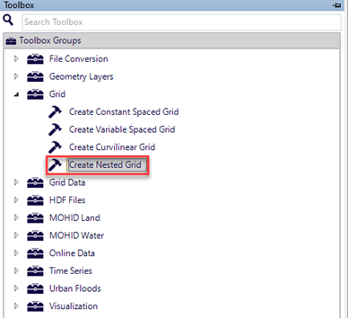
The first step to nest a sub-domain is to create a nested grid. OpenFlows FLOOD has a specific tool to create a nested grid which refines the horizontal resolution of a parent grid In the Map Window, and loads the parent domain Grid layer (which was used to create the parent domain Grid Data bathymetry file). Then go to Tools -> Grid -> Create Nested Grid.
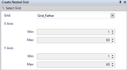
This will open the tool docked on the right-hand side of the Map Window. In step 1 select the parent domain grid from the drop-down list.
In step 2, select the button shown below.
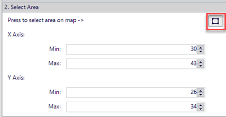
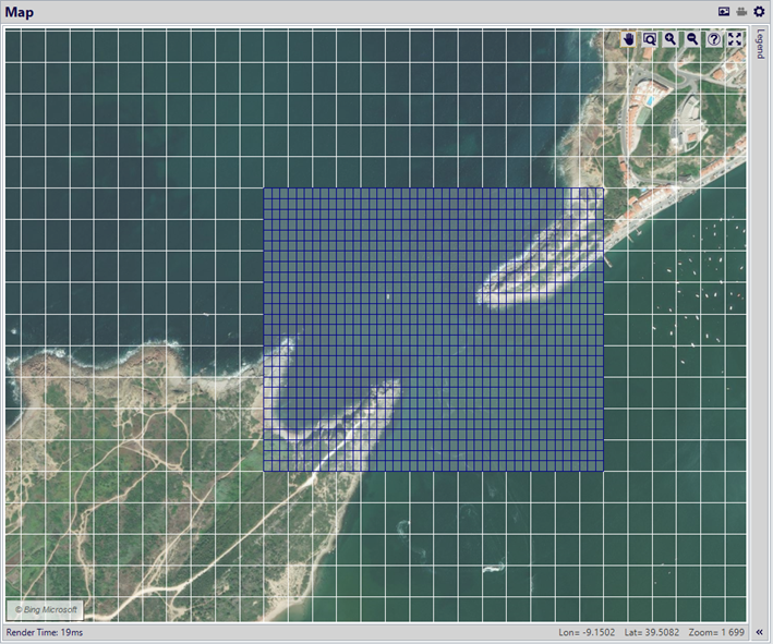
Then click and hold the mouse button over the map and draw a rectangle of the area where you want to refine the horizontal resolution of the parent grid. Release the mouse button to set the rectangle final area and a refined grid will appear in the map, as shown below. You can adjust the final location of the grid by changing the X and Y axis minimum and maximum grid indexes as shown in the image above.
Keep in mind that, generally the sub-model grid should be contained in the parent grid (there are some exceptions, but mostly it should be kept inside the parent’s grid). Also, avoid placing the open boundary of the sub-model grid over intertidal areas as this can bring some inconsistencies in some types of applications. If this is not possible to avoid, there are tools to help keep the consistency between the parent and child models.
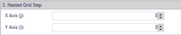
Once the sub-model area is defined you can increase the resolution ratio between the parent and child grids. The default and recommended ratio is 1:3 and should never be more than 1:5.
Finally, press the button in step 4 to save the grid file.
Keep in mind that the sub-model grid inherits the parent’s grid coordinate system and rotation angle. Especially when using grids defined in geographical coordinates (WGS84), the parent and child computational grid must be internally projected onto metric coordinates by the numerical engine. To ensure that the projection of both grids is made in a way that the nesting is correct, the projection reference point must be the same in both grids. Thus, after creating the nested grid please follow these steps:
- Open the parent and the child’s Grid file in a text editor (e.g. Notepad, Notepad++, etc.)
- Select the lines containing the keywords LATITUDE and LONGITUDE from the parent Grid and copy them to the child’s Grid replacing the existing ones. This way the lat/lon coordinates of the projection reference point is the same for both grids.
Once your nested grid is created, it’s time to create the bathymetry Grid Data file based on the new nested grid. This is done following the exact same procedure as one would create the parent’s bathymetry Grid Data file. See more information here.
After setting up, and calibrating and validating the parent domain, in OpenFlows FLOOD’s Explorer window select in the parent domain in the tree view. Right click and select “Insert Nested Domain”.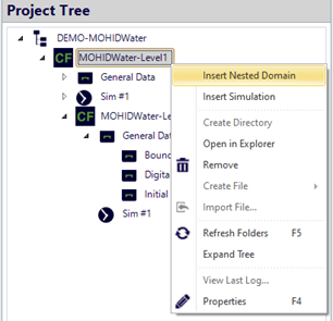
Then provide a name for the nested sub-domain and define the path to the child domain bathymetry Grid Data file.
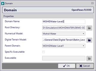
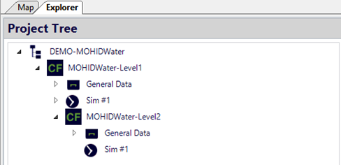
You can notice that the “Numerical Model” and the “Root Directory” are automatically handled by FLOOD and cannot be edited. Also, the “Parent Domain” field is now populated with the name of the corresponding parent domain. Press OK and a new nested domain is created in the domains/simulations tree view as shown below (parent Level 1 and child Level 2) and then select the nested domain, right-click and insert a new simulation.
Next, configure the new nested grid simulation. Make sure to check if the initial and end dates of the nested simulation are the same as the parent’s simulation. Also adjust the integration time step of the child simulation taking into account that the grid resolution is higher, thus most likely the time step will need to be reduced. Keep in mind that the parent and child time steps must be multiple. Find more information on how to define the model time step here.
In the nested simulation Hydrodynamic module configuration activate the sub-model options as shown below:
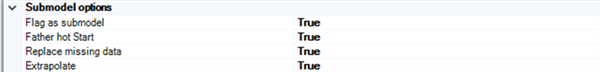
The “Father hot start” and “Extrapolate options” are recommended if the child simulation starts from a dynamic situation computed by the parent domain, e.g. the parent domain runs a “spin-up” period of 5 days and then the child simulation is nested only at the start of the parent’s domain continuation simulation. This way the sub-model will perform a “hot-start” interpolating the parent domain’s dynamic solution and using it as the initial condition.
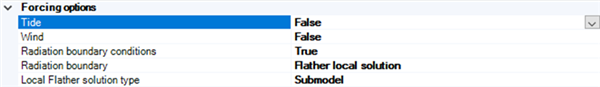
Also make sure that the Tide option is set to False in the nested simulation, as tide is only imposed as a boundary condition for the parent domain. The child domain receives the water elevations computed by the father model and it will not read the tidal forcing (e.g. FES2014, etc.).
If the physical forcing in the parent and child’s domain is very similar, as well as the vertical resolution and general configuration then there’s no need for further configurations and the nested simulations are ready to be computed. Otherwise, it might be necessary to setup additional options, for example, configuring radiation boundary conditions like Father with sub-model local solution to address possible inconsistencies between the water elevations provided by the parent domain and the ones computed by the child domain.
Or using a flow relaxation scheme to handle velocities at the open boundary.

Regarding the vertical discretization of the nested domain, it can be different from the parent domain, e.g. you can have a parent domain with 10 vertical layers and a child domain with 30 layers. Both domains can also use different types of vertical discretizations, e.g. Sigma, Cartesian or hybrid.
In OpenFlows FLOOD 10.03, the child domain bathymetry Grid Data file should be placed in its corresponding “General Data/Digital Terrain” folder and the path referenced to this location. However, it must also be placed in the parent’s domain “General Data/Digital Terrain”. This duplication is needed in the current release (10.03) of OpenFlows FLOOD but will be unnecessary in future versions. The same may apply for some other files like Discharges and Time Series configuration files that are specific to the child simulation.
Once the child domain simulation is setup, to compute the parent and child simulations using nesting approach go to Execute Models tab and click Schedule.
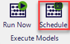
The following dialog will appear.
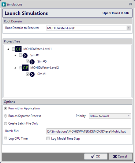
Select the root domain to execute and in the project tree, select parent and child simulations check boxes. Finally press OK to start the simulation.
See Also