| Product(s): |
WaterSight |
| Version(s): |
10.00. |
| Area: |
Documentation |
Minimum required data
In order to have the pumps dashboards with meaningful information, the minimum recommended data is the following:
- Flow signal for each pump or for the all pump station;
- Discharge pressure signal for each pump or for the all pump station OR level signal of the downstream tank;
- If flow and head is only available for the all pump station, then pump status signal for each pump is required;
- Pump curves (flow-head and flow-efficiency);
- Information if pumps are variable speed or not;
With this information it will be possible to show the head curves graphs (including the curve and calculated operating points), the efficiency curves graphs (including the curve and estimated operating points) and the power curves graphs (including the estimated operating points). Also estimated efficiencies for each pump are displayed.
Therefore having a power signal is not required, but instead is good to have as it will allow to more accurately calculate flow-efficiency operating points, the power-flow operating points and also each pump efficiency. Below is summarized the additional information that would be helpful to have (but not required):
- Suction pressure signal (it can be ignored or a suction signal can also be estimated using WaterGEMS -by creating a derived signal. If you have doubts, please reach to your Bentley contact);
- Power signal and curve;
- If variable speed pump, variable speed efficiency curve and speed signal;
Calculating Pump Head
When calculating pump head, the following cases might exist:
- Discharge tank level and suction level available - for this case the reference elevation of both sensors is required (information filled in Admin >> sensors)
- Discharge pressure and suction pressure available - if reference elevation for both sensors is not provided, WaterSight assumes they are located at the same reference elevation (information filled in Admin >> sensors)
- Discharge tank level and suction pressure available - for this case the reference elevation of both sensors is required (information filled in Admin >> sensors)
- Discharge pressure and suction level available - for this case the reference elevation of both sensors is required (information filled in Admin >> sensors)
- Only discharge pressure available - in that case suction signal is ignored and assumed to be roughly 0 - for example the pump is roughly at the water level. It is also possible to estimate the suction pressure by creating a derived signal in WaterGEMS (in that case reach to your Bentley point of contact for more information). Reference elevation is not required.
- Only discharge tank level is available - in that case pump head is not calculated as there is not enough information.
Images below illustrate the 6 mentioned cases:
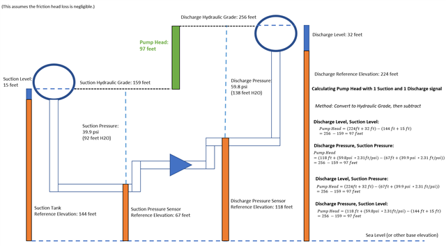
Figure 1 - Pump head calculation examples for use cases 1 to 4
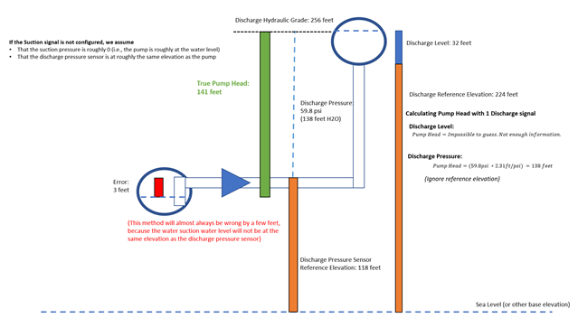
Figure 2 - Pump head calculation examples for use cases 5 to 6
Pump measurement VS Pump station measurement
Two different cases may exist:
- Sensor measurements are available for each pump (minimum required is pump flow and head);
- Sensor measurements are available at the pump station level (minimum required is pump station flow and head) and status (on/off) is available for each individual pump;
WaterSight can automatically handle and calculate operating points for each individual pump for both use cases 1 and 2. In case sensor measurements are available for each pump, flow and head operating points are accurately calculated (represented with blue dots in figure below). Head is calculated based on pump discharge pressure or downstream tank level and suction pressure (this last one is optional).
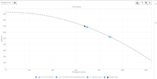
Figure 1 - Flow and head operating points based on actual measured pump flow and head (appearing as blue circles)
In case SCADA measurements are only available at the pump station level and status for each individual pump is also available, operating points for each pump can be estimated. For the time-steps where at least two or more pumps are on simultaneously, the flow-head operating points for those pumps that are on will be estimated based on the total pump station flow and head (represented with blue crosses in figure below).
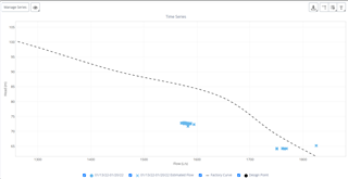
Figure 2 - Flow and head operating points estimated based on the total pump station flow and head (appearing as blue crosses)
For the time-steps where only one pump is turned on (and all other pumps are off), then it is assumed that the total pump station flow and head correspond to that specific pump that is on, and in this case flow-head operating points are accurately calculated (represented with blue dots in Figure below).
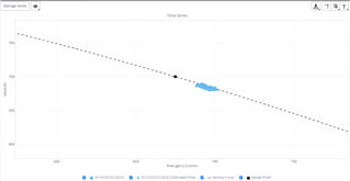
Figure 3 - Pump Flow and head operating points are equal to the total pump station flow and head, in case only one pump is on (appearing as blue circles)
The pump signals configurations and other characteristics are done in the pumps administration page. Reference elevations for the associated pump sensors may also be required (information filled in Admin >> sensors).
For configuring case 1 above, the user just need to complete in the pump administration page the specific information and signals for each pump (configuration example below).
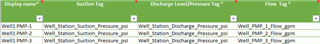
Figure 1 - Each pump has its own flow signal.
For configuring case 2, in the pumps administration page the user needs to assign for each pump:
- the the total station flow and head
- the specific status of each pump (configuration example below)
- plus the pump station information.
For the time-steps where at least two or more pumps on simultaneously, the flow-head operating points for those pumps that are on will be estimated based on the total pump station flow and head. For the time-steps where only one pump is turned on (and all other pumps are off), then it is assumed that the total pump station flow and head correspond to that specific pump that is on, and in this case flow-head operating points are accurately calculated.
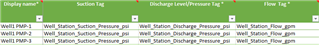
Figure 2 - Pumps share the same flow signal (assuming pumps in parallel).. Please note that flow signal for each pump is the total station flow.
For more information about interpreting the various pump curve graphs, click here.
See also
Filling reference elevation for sensors - Admin sensors
Pump Details
Pumps Administration page
Prioritizing Pumps
OpenFlows WaterSight TechNotes and FAQ's