| Product(s): |
WaterSight |
| Version(s): |
10.00. |
| Area: |
Documentation |
Creating a live Digital Twin of the system
Direct measurements from SCADA or other telemetry systems together with demand patterns calculated within the application can be used to override and adjust model boundary conditions and with this turning the typical static hydraulic model into a real live digital twin, a real time hydraulic model of the system, and contributing to increase the confidence and accuracy in the model calculated results. The user can now investigate the real-time performance for each asset and use the most updated model to simulate emergency events such as pipe breaks, fires, pump shutdowns and valve closures.
As previously mentioned, WaterSight allows to:
- Set the initial conditions for the model run, based on the real time sensors measurements
- Adjust patterns such as demand patterns and HGL patterns at tanks and reservoirs for the all simulation period
WaterGEMS model setup
In order to have the initial conditions imposed to the instant corresponding to the start of the simulation or in order for the user to directly compare modeled data with measure data, it is required that in the WaterGEMS model that is uploaded to WaterSight (under Administration >> Numerical Models):
- SCADA signals are listed, and their name match exactly the sensor tags sensor administration page of WaterSight
- SCADA signals units match the units defined for the sensors in the sensor administration page of WaterSight
- SCADA elements are created in the model
- SCADA elements are configured:
- associated to the model element;
- field defined;
- SCADA signal defined;
- If Control Overrides are desired for the Hindcast period, Set the Control Overrides option in the model to True.
- When using the automatic demand adjustment option of WaterSight (see below for more information) it is required that the zones name in the WaterGEMS hydraulic model are associated to the nodes and match the names given to the zones in WaterSight.
- Update the calculation within WaterGEMS. Go to Home >> Options and procede with the following additional configurations:
- Calculation Type: SCADAConnect Simulator
- SCADA Calculation type: "Hydraulics only", if only running hydraulics; "Age, Constituent & Trace" if running both hydraulics and water quality analysis (in case of a constituent analysis the user needs to define the constituent properties and the concentration at the sources in the WaterGEMS model. Also make sure to define a trace node in WaterGEMS - like for example a tank or Reservoir - otherwise the model will not run). More information about the workflow to set up age and constituent analysis in WaterGEMS, take a look here. For more detailed information about defining constituent properties in WaterGEMS, take a look at this article.
- Simulation mode: needs to be set to Historical
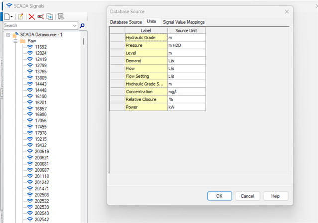
Below an example of the SCADA signals name/tags and units in WaterGEMS (that need to match those defined in the sensor administration page of WaterSight)
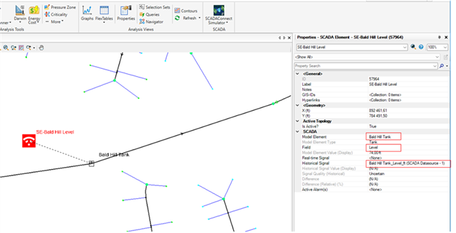
Below an example of a SCADA element created in the WaterGEMS model and mapped to the associated model element (in this case tank level).
The video below describes and demonstrates how to prepare a WaterGEMS model for real time simulation in WaterSight.
For more information on how to configure SCADA elements in WaterGEMS, you can also take a look at this article: Using the SCADA element
Imposing initial conditions to the hydraulic model based on sensors measurements
The sensors measurements that can be used to override the initial conditions of the hydraulic elements are the marked as Yes in the below table. All the other attributes listed in the table, even those that can not be used to override the initial conditions for the hydraulic model, can always be used to compare model results with the real measurement results.
Table 1 - sensor measurements types that can be associated with hydraulic model elements
|
Element Type
|
Attribute
|
Can be used as Initial Setting for the model runs?
|
Can be used to compare model results with sensor results?
|
|
Reservoir
|
Hydraulic Grade
|
Yes
|
Yes
|
|
Junction
|
Pressure
|
No
|
Yes
|
|
Hydraulic Grade
|
No
|
Yes
|
|
Demand
|
No
|
Yes
|
|
Concentration
|
Yes
|
Yes
|
|
Pump
|
Concentration
|
No
|
Yes
|
|
Flow
|
No
|
Yes
|
|
Hydraulic Grade (From/To)
|
No
|
Yes
|
|
Pressure (From/To)
|
No
|
Yes
|
|
Pump Status
|
Yes
|
Yes
|
|
Relative Speed Factor
|
Yes
|
Yes
|
|
Wire Power
|
No
|
Yes
|
|
Pipe
|
Flow
|
No
|
Yes
|
|
Pipe Status
|
Yes**
|
Yes
|
|
PRV/PSV
|
Concentration
|
No
|
Yes
|
|
Flow
|
No
|
Yes
|
|
Hydraulic Grande (From/To)
|
No
|
Yes
|
|
Pressure (From/To)
|
No
|
Yes
|
|
Valve Status
|
Yes**
|
Yes
|
|
Hydraulic Grade Setting
|
Yes
|
Yes
|
|
Pressure setting
|
Yes
|
Yes
|
|
FCV
|
Concentration
|
No
|
Yes
|
|
Flow
|
No
|
Yes
|
|
Hydraulic Grande (From/To)
|
No
|
Yes
|
|
Pressure (From/To)
|
No
|
Yes
|
|
Valve Status
|
Yes**
|
Yes
|
|
Flow Setting
|
Yes
|
Yes
|
|
TCV
|
Concentration
|
No
|
Yes
|
|
Flow
|
No
|
Yes
|
|
Hydraulic Grande (From/To)
|
No
|
Yes
|
|
Pressure (From/To)
|
No
|
Yes
|
|
Valve Status
|
Yes**
|
Yes
|
|
Relative Closure
|
Yes
|
Yes
|
|
Headloss Coefficient Setting
|
Yes
|
Yes
|
|
GPV
|
Concentration
|
No
|
Yes
|
|
Flow
|
No
|
Yes
|
|
Hydraulic Grande (From/To)
|
No
|
Yes
|
|
Pressure (From/To)
|
No
|
Yes
|
|
Valve Status
|
Yes**
|
Yes
|
|
Tank
|
Level
|
Yes*
|
Yes
|
|
Hydraulic Grade
|
Yes*
|
Yes
|
|
Concentration
|
No
|
Yes
|
|
Tank Status
|
No
|
Yes
|
* The tank definition in the model must match the SCADA type. If the SCADA signal is Level, the tank "Operating Ranging Type" should be defined by Level. If HGL, then tank "Operating Ranging Type" should be defined by Elevation.
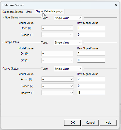
** For Element Statuses, the Sensor used by WaterSight should have the following number based coding in order to represent when a element is Active, Closed, ON, OFF, etc.:
- Valve Status: Active = 2, Inactive= 1, Closed = 0
- Pipe Status: Open = 1, Closed = 0
- Pump Status: ON = 1, OFF = 0
Notice that this coding is different to what is assumed in WaterGEMS by default, therefore to use the information from Status sensor in simulation runs in WaterSight, it's needed to set up the Signal Value Mappings in SCADAConnect tool as shown below (click here for more information on WaterGEMS's SCADAConnect tool).
Initial conditions, based on sensors data (those marked as Yes in the above table), will be always imposed to the instant corresponding to the start of the simulation. The start of the simulation is illustrated below:
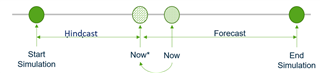
Whenever a new simulation is triggered (Now), the simulation start and end time are set by:
- Defining a new Now*, which Now rounded down to the previous full hour
- The start of the simulation is the Now* - the hindcast period.
- The end of the simulation is Now*+ the forecast period.
In case the user wants to use in the model runs the initial conditions from SCADA for the Now instant, the user should set an hindcast period of zero. Please note that the sensor values used for the model initial conditions corresponds to the processed 15 minutes time series and not the raw sensor time series. The processed 15 minutes time series already has some cleanup, so this can minimize some outliers being considered for the model runs and affecting all the model results.
Comparing sensor data with modeled data
As mentioned above, it is also possible to directly compare measured data with modeled data (in case SCADA elements are created and mapped in the WaterGEMS model file, see above). Once sensor elements are configured in the hydraulic model and associated to the model element, then it is possible to directly compare in the same graph the real sensor measurements with the modeled results to check the accuracy of the hydraulic model. It is important to highlight that this comparison can be done for any sensor that is associated with a hydraulic model element - any sensor type that is contained in the table 1 above.
This means that although some sensors can not be used to override the model initial conditions, those can be used to directly compare the modeled results with the real time measurements. For example this can be particularly useful to directly compare sensor data from flow meters or pressure meters with model results data. For that you need to create a SCADA signal element in WaterGEMS and assign it to a junction (if pressure) or to a pipe (if flow). For both examples the sensors measurements will not override the initial conditions of the hydraulic model elements, but can be useful to compare model and measured data at those locations.
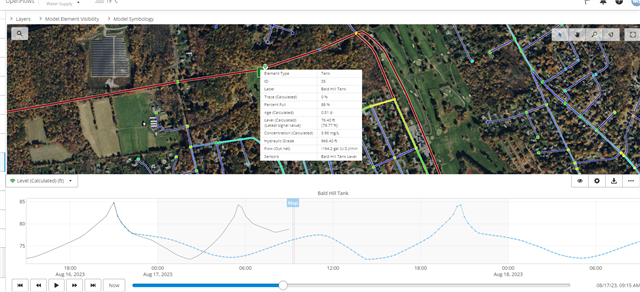
To see the comparison between the modeled and measured data, please go to the Current Simulation page or the Operational Response simulation page, and click in one of the model elements that has a sensor wi-fi icon associated. When clicking in one of these elements, two lines will be displayed in the graph: black line corresponding to the sensor measurement and the blue line corresponding to the model result. Directly comparing these two lines at some points of interest allow the user to understand how calibrated and accurate the model can be. Using the measurement dropdown located on the top left of the graph allows to change the measurement that is displayed in the graph for the specific selected element.
Another important note: if the black and the blue line match the exact same value for the initial time step of the model run (when the blue line starts), then it means that sensor data is being used to set the initial conditions for the model run. In case there is a gap between the value for the initial timestep of the model run and the sensor data, then the sensor data is not being used to actively set the initial conditions of the model.
Adjusting demand and HGL patterns in the model for the all simulation period
Furthermore, pattern adjustments can also be automatically applied (and in this case to all period of the simulation) in case demand adjustment option or hydraulic grade line adjustment option are enabled in the Numerical Models administration. The HGL adjustment functionality is particularly useful when using hydraulic models of distribution systems in WaterSight that do not cover the transmission line.
For more information about automatic demand adjustment, please click here.
For more information about HGL pattern adjustment, please click here.
See Also
Numerical Model Administration
Automatic Demand Adjustment
Automatic Hydraulic Grade Adjustment
OpenFlows WaterSight TechNotes and FAQ's