| Applies To |
|
| Product(s): |
PondPack, SewerGEMS, CivilStorm |
| Version(s): |
08.11.XX.XX and higher (PondPack), 08.11.04.54 and higher (SewerGEMS/CivilStorm) |
| Original Author: |
Scott Kampa, Bentley Technical Support Group |
Overview
The purpose of this TechNote is to discuss how to set up and use PondMaker. Additional information can be found in the PondPack Help menu.
Note: PondMaker is also available in recent versions of CivilStorm and SewerGEMS. The Implicit or Explicit solver is required to analyze pond routing and utilize PondMaker in CivilStorm or SewerGEMS.
Additional information can be found in the PondPack Help menu.
For a video demonstration, see embedded video at the bottom of this article.
Background
In the development of a given area of land, flow will often increase since pavement is less pervious than the pre-development land. Ponds and pond outlet structures are used to mitigate this, introducing storage and controlled flow to try to keep the peak flow close to the pre-development conditions.
PondMaker is a feature that streamlines detention pond design by guiding you step-by-step through this process. Once completed, the storage and outflow from the post-development pond should be within the give tolerance of the pre-development conditions. PondMaker also assists by keeping track of information such as target outflows, pond volume estimates, outlet structure design trials, peak pond outflows, and maximum water surface elevations for multiple storm events and/or multiple ponds. With the click of a button, the numbers in this spreadsheet update automatically.
The PondMaker Dialog Box helps organize and reduce pond design iterations by systematically guiding you through the following iterative pond design sequence, including estimating pond storage requirements, creating pond dimensions, outlet design and analysis, and routing analysis.
Note: PondMaker is available in older releases of PondPack as well, such as PondPack V10. This TechNote covers only PondMaker as used in PondPack V8i, or SewerGEMS and CivilStorm. Consult your Help documentation in PondPack V10 for steps to use PondMaker in that version.
Note: this tool assumes that you are trying to attenuate the peak flow of your site outflow hydrograph to be below the peak of the predevelopment conditions. If this does not match your use case, PondMaker may not be appropriate. Also note that you do not necessarily need to use PondMaker for pond sizing - you can simply set up an estimate of the pond dimensions and outlet, run the model, assess, then adjust as needed and repeat.
Before using PondMaker
PondMaker will help design ponds and outlet structures, but you must have a working model to start, with both pre- and post-development scenarios set up. You will not need to set up pond dimensions or the elements in the composite outlet structure in the post-development scenario, however the elements must be in place.
Note: For a new model, PondPack has a feature to help set up pre- and post-development scenarios. This feature opens when you select to create a new model. You can also access this tool from the Scenario manager. If you do not know the pre-development conditions but have the target peak flow rates, it is only necessary to define post-development scenarios.
Start out by laying out the pre-development conditions. At minimum, this will include a catchment and an outfall. You will also need to have the storm data set up for the scenario you are modeling.
Next, you will need to set up the post-development scenario. In a new scenario, enter the new CN and time of concentration information for the post-development catchment. You will need to add a pond, pond outlet entrance node and the pond outlet link. PondMaker will aid in creating the pond dimensions and setting up the outlet structure.
Within PondPack, assign the Pond Type as “No Volume” and the pond outlet attribute “Has Outlet Structure?” to “False.”
Within SewerGEMS or CivilStorm, set the pond type to elevation-area and initially estimate approximate values. We suggest using the allowable top area as the maximum area of the pond and use the ground elevation of the pond’s banks for the maximum pond elevation. The estimated depth can be used to determine the base elevation (pond bank elevation minus pond depth) with an assumed base area. These are initially guesses, PondMaker will overwrite the dimensions in the design process . Set the pond outlet attribute “Has Outlet Structure?” to “No”.
Note: PondMaker requires the use of the scenarios and alternatives. For more information, see the TechNotes on Scenario Management and Active Topology Selection. You can also look at the PondPack sample “Pre and Post Pond Design.ppc” found at C:\Program Files\Bentley\PondPack8\Samples. This sample file includes a pre- and post-development scenario for two storm events, and utilizes scenario management and active topology selection in modeling the system.
Using PondMaker
Once you have the pre- and post-development scenarios created for each return event, we will be ready to use PondMaker. To access PondMaker, go to Tools > PondMaker, click the PondMaker icon above the drawing pane or Right click your pond and choose "Design Pond with PondMaker". This will open the PondMaker dialog.
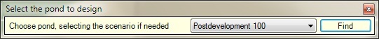
To start a new PondMaker session, click the New icon in the upper left corner. A selection tool will open, prompting you to select a pond. Note that the selection tool allows you to choose a post-development scenario as well. This is in case your model has the pre-development scenario active, where a pond may not be visible for selection.
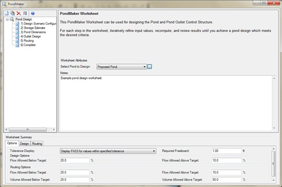
Once the pond is selected, a new item will appear in the list on the upper left along with six steps. At the bottom of the dialog is a table that will be filled as you go through these steps. In the Options tab of this table, you can set up the tolerances you wish to use during the PondMaker process.
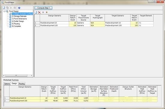
“1) Design Scenario Configuration”. This step allows you to choose the design scenario, which is typically the post-development scenario, and the source of the flow or volume that PondMaker is trying to match. Basically, it establishes the pre-development target flows and post-development hydrographs. If you choose “Scenario,” you can then choose the target scenario, which will be the pre-development scenario. If you choose “Hydrograph,” the option to select a user-defined target hydrograph will become available. If you choose “User-defined,” you will be able to enter your own value for the target peak flow and volume in the table at the bottom of the PondMaker dialog.
When choosing "Target Element", ensure that the selected element is active in both the predevelopment (target) and postdevelopment (design) scenarios, as this is where the peak flows is obtained from.
Once you have made your selection for the target flow/volume, select Compute Step 1 at the top of the dialog. Choose the Design tab in the table at the bottom of the dialog. You will see that results for Target Peak Outflow, Target Outflow Volume, Peak Pond Inflow and Total Inflow Volume.
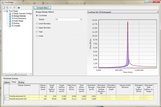
Next, “2) Storage Estimate.” This step uses the calculated post-development inflow hydrograph and the target peak flow found in Step 1 to estimate the storage volume for the pond. Select the storage estimate method and select the Compute Step 2 button at the top of the dialog. The post-development inflow hydrograph and the target pond outflow curves will be generated. The estimated storage will be shaded in blue and populated in the table at the bottom of the dialog.
This estimate basically assumes that the pond you ultimately design will have a peak outflow equal to the target peak flow and that the shape of the rising limb of that outflow hydrograph will look similar to the blue line. The shape/curve of the blue line is based on the selected method, which defaults to curvilinear.
Next, “3) Pond Dimensions.” This step allows you to enter the pond dimensions manually or have PondMaker develop the dimensions for you. To enter the data yourself, fill in the selected property data, such as the Pond Type. The pond type selection will determine the other attributes displayed. For instance, choosing “Elevation-Area” will show a cell that allows you to enter an elevation-area curve. Choosing “Pipe” will allow you to enter the pipe storage information.
The alternative would be to allow PondMaker to select the pond dimensions based on a set of parameters. To use this method, choose the “Generate Dimensions” button. A new dialog will open.

You choose which dimension you want PondMaker to compute and then fill in the necessary fields at the top portion of the dialog. For computing Pond Area, you would enter data for pond water depth, side slope, freeboard depth, and top elevation. When you select the Compute button in the bottom left, the results fields will be populated. PondMaker will basically take the "knowns" that you've entered and fit in the estimated storage volume from the previous step to compute the unknown. Select Okay, and you will be prompted if you want to include the data in the PondMaker worksheet.
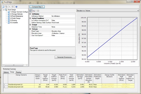
Once the pond data is entered, select the “Compute Step 3” button. A curve will be generated to the right of the property data. You can use the dropdown menu above the curve to view either the elevation-area or elevation volume curve. In the table at the bottom of the dialog, values for “Estimated Max Water Surface Elevation” and “Freeboard Depth” (which will be “True” or “False” depending on the parameters in the options tab) will be entered. If you've manually entered trial pond dimensions and the estimated max water surface elevations is not acceptable, revise your pond dimensions and click the "Compute Step 3" button to update the worksheet. PondMaker is basically filling the entered pond with the estimated storage volume from the previous step and reporting the resulting water surface elevation.
Next, “4) Outlet Design.” This step allows you to create an outlet structure for your pond that will attenuate the pond outflow down to the target pre-development peak. This step may take some trial and error to find the right combination and set up of the outlet structure. PondMaker will allow you to save multiple trials so that you can compare different results and find the best solution.
Note: free outfall is assumed for the tailwater in this step, as routing through the network does not occur until step 5. If you expect significant tailwater effects downstream of the pond outlet, this can introduce significant additional restrictions of pond outflow that would not be evident until step 5 (routing).
To start, click the New icon in the worksheet and choose “Composite Outlet Structure.” A new composite outlet structure will appear, which can be renamed. Next, enter the maximum and minimum headwater for the composite outlet structure. This will typically correspond with the upstream pond.
Now you will add the components of the composite outlet structure. To do this, highlight the composite outlet structure name and select the New icon. Then choose the type of outlet structure you wish to add (riser, weir, culvert, etc.). The selected structure will then appear below the composite outlet structure name. The dotted tree structure indicates that it is associated with the composite outlet structure.
Highlight the individual outlet structure and fill in the appropriate data in the properties just below it. Each type of outlet structure will have its own set of data, so if you add more than one item to your composite outlet structure, be sure to fill in the data for each one.
Once completed, if you want to see the rating curve for your composite outlet structure, you can highlight the composite outlet structure name and then select the green Compute icon. The rating curve will appear in the table. You can also look at the rating table or the rating curve or rating table of each individual outlet structure by highlighting it in the list.
Then choose the “Compute Step 4” button. The “Estimated Peak Outflow” and “Estimated Peak Outflow vs. Target” cells will fill in.
Note that the graphical display in this step is designed to help you quickly see how close your trial outlet was to achieving the goal (attenuating the pond outflow down to the target peak without exceeding the desired freeboard). The horizontal dashed lines represent the estimated maximum water surface elevation for each return event and the orange line represents the "target" rating curve, connecting the max WSE lines at the pre-development target flows. Basically in order to achieve your goal, you'll need to get your trial outlet structure's rating curve as close as possible to the orange target rating curve. More information on the target rating curve is found in the next paragraph.
The Target Rating Curve represents the curve that you would need to closely match to the designed outlet rating curve, to get close to the target predevelopment flow rates. It is a line, so it needs to connect between at least two points, so you will need to have at least two return events in your PondMaker worksheet in order to see the line. Those points on the target rating curve are the pairs of target predevelopment peak flow and corresponding estimated water surface elevation. Typically you would design a pond for multiple return events, for example lower events like 10 and 25 year to align with lower outlet components like orifices/culverts and risers, then a higher return event like 100 year, to design for the emergency overflow weir for example.
If the “Estimated Peak Outflow vs. Target” fails, you may want to go and try another trial for the composite outlet structure. Select the New icon and select “Composite Outlet Structure” again. Choose a new set of outlet structures (or revise the data you used previously). Once completed, change the dropdown beside “Trial Outlet Structure” to the new composite outlet structure and select “Compute Step 4.” Continue this until you are satisfied with the results.

Next, “5) Routing.” Where the other steps used estimates to find calculated results, this step will actually compute the simulation and route hydrographs through the network, allowing you to see the final results for this setup. Choose the outlet structure from the “Trial Outlet Structure” dropdown and select the “Compute Step 5” button. The results will be viewable in the Routing tab in the table at the bottom of the dialog. If you want to test other outlet structures, simply choose the one you want from the dropdown and re-compute.
Note:
- Since steps 1-4 use estimated values, there can be cases where the estimate will be within the tolerance but the final results from Step 5 will not be. Be sure to review the results before exporting the data from PondMaker out to your scenario.
- Also, when using vortex valves as the composite structures with linear storage option in step 2 of the storage estimate, please check if your hydrograph of vortex follows a linear pattern or not. If not, then you might need to consider other storage estimate methods like curvilinear estimate so as to get close results for the outlet design step and routing step and to model the correct dimensions/levels for the outlet structure

If you are satisfied with the results, highlight “6) Complete”. The designed pond and outlet structure will not be exported to your model unless you do this step. To finalize, click the Export to Scenario button. Once you do this, you should see the data from PondMaker in the pond and pond outlet elements in the model. You can also view a report of each step of the process by clicking the Report button
Note: PondMaker is just a "sandbox" so you need to run the exported scenario in order to get the results from that scenario.
There is additional information on PondMaker in the PondPack Help documentation. You can also find a Quick Start Lesson that walks through the process. You can access this by going to Help > Quick Start Lessons. There is also a sample file that has a completed PondMaker worksheet. You can find this by going to C:\Program Files\Bentley\PondPack8\Samples and choosing “Pre and Post Pond Design.ppc”.
Video Demonstration
A copy of the starter model file for this video can be downloaded here.
See Also
How can I set up pre and post development scenarios for use in pond design with PondMaker?
Using PondMaker with different tailwater for each return event
What do all the lines in PondMaker step 4 represent?
Accounting for bypassed (undetained) flow in PondMaker
Pond Design from Start to Finish with PondPack (Webinar Recording)