| Product(s): |
WaterGEMS, WaterCAD |
| Version(s): |
CONNECT Edition, V8i |
| Area: |
Modeling |
Problem
How can a user fix the WaterGEMS or WaterCAD error message "Network Unbalanced" or "Cannot solve network hydraulic equations". "Unexpected reverse flows" may be encountered as well.
Note: for unbalanced pressure subnetworks resulting on "convergence not achieved" in SewerCAD (of the GVF-Convex solver in SewerGEMS), see: Convergence NOT achieved Message when computing StormCAD or SewerCAD model
Background
The "Network Unbalanced" and "Cannot solve network hydraulic equations" user notification means that the program could not converge on a balanced solution within the maximum number of trials. The difference between these is that the "Network unbalanced" message can occur for individual time steps, while the "Cannot solve network hydraulic equations" does not specify a time step where the issue occurs.
Between calculation iterations, the program checks the relative change in flow, which has a default value of 0.001. If the relative flow change is below the "Accuracy" value designated in the calculation options, the time step is balanced or is said to have converged. If the relative flow change is greater than the Accuracy value, the program will try another iteration. If the program reaches the maximum number of trials without finding a solution, the "Network Unbalanced" user notification is generated.
Solution
Check Connectivity
The first thing to do is to check to make sure your entire network is connected properly and that you do not have elements that are physically disconnected from a source (tank or reservoir). Perform a validation (Analysis > Validate) on the model to see if there is information on possible issues in the model. If there are messages that are related to specific elements, double-click on it or right-click and choose "Zoom To", which will select the element in the drawing pane. Check the properties and setup of the element to see if there are issues related to data entry or orientation. If the element is a node, you can click and drag the element to make sure it is connected to all the pipes it is supposed to be connected to. Nodes that are not connected to pipes can occur if you used ModelBuilder to create the model. If your junctions are not connected properly you can use the Batch Pipe Split tool, which will allow you to connect the junctions to the pipes they are supposed to be connected to by splitting them.
The Network Navigator tool can help you locate topological issues. (check the "See also" for two links on this)
Check general model setup
If there are not validation issues, make sure the setup of elements are accurate. Pay close attention to logical controls, valve settings, and valve status, empty or full tanks, and near zero flows as these are common causes of the issue.
If you have a check valve on the pipe directly downstream of a pump, consider removing the check valve. In WaterGEMS and WaterCAD, a pump will not allow reverse flow. A check valve on the downstream pipe is redundant and can sometimes impact the model calculations.
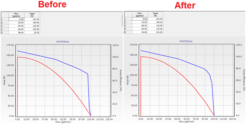
Multi-point Pump Curves
If you are using the multi-point pump curve type for one or more pumps, sharp changes in the curve can make it difficult for the numerical solver to settle on the correct operating point for the pump. This can be especially problematic if the calculation option "Use Linear Interpolation for Multipoint Pumps" is set to "true". Setting this to "false" will smooth out the curve. If this results in a curve that is too far from what you need to model, consider an alternate approach of manually smoothing any sharp points in the pump curve by adding additional points. See example below.
Variable Speed Pumps
If you're using a VSP or VSPB element, carefully check the target element and target HGL/flow. Consider what you have downstream of the pumps, such as a tank's elevation or the sum of the downstream demands.
If you have multiple fixed or variable speed pumps (VSP) discharging into the same pressure zone, this can also cause numerical instability. If the real system includes some manual operation of the pumps in this case, consider matching that in the model by using time based controls or a pattern (is variable speed pump = true, type = pattern).
Check for zero or near-zero flows
If you have a significant portion of your model with zero flow (such as the case when modeling "static" conditions), the numerical solver will have a hard time converging on a balanced solution. The reason is because the relative flow change between trials will typically be large in this case, since the numbers that it is dealing with are very close to zero. Check the link in the "See Also" section below for more on this.
Bad Friction / Roughness coefficient
Check the Friction Method selected in the calculation options and ensure that the friction factor is set appropriately. For example with the Darcy-Weisbach friction method, the Roughness Height value is used to determine headloss, and a typical value is on the order of 0.0009 feet. If the friction factor is set far outside normal range, the numerical solver may not be able to balance energy across the model.
General Purpose Valves (GPVs)
If you have GPV' check the "Flow Demanded" from the calculation summary (Analysis > Calculation Summary) at the time step of the red user notification. If the flow going to that GPV is not enough to provide the flow demanded examine the GPV headloss curve to make sure the maximum value of the curve is large enough to cover that flow. For example, if the flow demanded is 850 gpm check the largest value on the curve is at least 851 gpm.
If the model is still unbalanced when using one or more GPVs as backflow preventers, you may need to add additional points to the GPV headloss curve to "smooth" the transitions, reduce the value of the first positive headloss value at the zero flow point (second row in the screenshot above), consider simplifying (for example use a PBV instead) or adjust the advanced calculation options per the above guidance.
Top Fill Tanks
Confirm that tanks have the proper elevation data, including any top-fill tanks that may be in the model.
Intra-Trial Status Messages
For EPS simulations you might find more clues to solving your problem by either:
1. (if you have V8i SELECTseries 5 or greater) - Click the time step in question in the Calculation Summary, then click the Intra-Trial details tab. This identifies elements that are changing status between trials
2. (if you have V8i SELECTseries 4 or earlier) - Open the .RPC file. This file contains a log of the trials that the program runs through when it is trying to converge on a solution. In order to open this file browse to the folder where your model is saved; that is where the .RPC file will be. You can open this file in a text editor, such as Notepad.
Look down the trial list until you start to see the trials where there are elements that are constantly changing status (for valves a status change may be going from "active" to "closed" or vice versa and for pumps it could be going from "On" to "Off") over consecutive trials. The elements that have a constantly toggling status could be a clue to where your problem lies. If this happens often for certain elements then your model may be to tightly constrained or controlled and you should attempt to simplify the model where possible.
If you are seeing many valves oscillating status in a particularly challenging timestep, this is an indication that their configuration should be checked, to ensure that they are correct and not accidentally "fighting against each other" due to the assumed settings. You might be able to adjust the configuration of those valves (in some cases with a conservative assumption) to make the model more simple and stable. In other words, try to address the root of the problem instead of tweaking the options to get it to work. This should be better in the long run if you can identify (with help from the intra-trial status messages) some changes that stabilize the model.
For example this article talks about challenges like this that can occur with PRVs in parallel.
Of course in some cases you may need to adjust the calculation options, in which case it does make sense to be extra cautious.
Pressure Dependent Demands
If you are using pressure dependent demands in your model or in a particular scenario, then check this additional article on PDD to check specific results which could give you this error.
Troubleshooting Pressure Dependent Demands with a network unbalanced user notification
Calculation Options
Several advanced calculation options are available to help with convergence in challenging situations where the model data input and topology has been checked. First, you can try increasing the number of trials. To do this, go to Analysis > Calculation Options. Under the "Steady State/EPS Solver" section, double-click on the active calculation option to view the properties. Find the property field "Trials" and set this to a higher value, such as 400. In many instances, this is enough to allow the program to find a viable solution. Note that the program will not necessarily run all 400 trials, but will only use the number of trials it takes to come up with a viable solution.
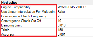
Other options to try changing
1. Engine Compatibility. The latest solver is "WaterGEMS 2.00.12". If you are using an older solver, using the latest may help as well.
2.. Convergence Check Frequency. This option sets the number of solution trials that pass during the hydraulic balancing before the status of pump, check vlaves, flow controls valves, and pipes connected to tanks are once again updated.
3. Convergence Check Cut Off. This option is the number of solution trials after which periodic status checks on pumps, check valves, flow control valves, and pipes connected to tanks are discontinued.
4. Dampening Limit. This is the accuracy valve at which solution dampening and status checks on PRVs and PSVs should begin. Change the value so that it is 10 times the accuracy. So if you have an accuracy of 0.001, set Damping Limit to 0.01.
If that doesn't work, you can also try to increase the Accuracy field (also in Calculation Options properties) to a higher value, such as 0.01. This will mean that the relative flow change between iterations can be higher, which may allow the program to find a solution. You do not want the accuracy value to be too high though, or it may compromise the results.
If you are using linear interpolation, you can try setting this to False, as shown in the screenshot below. This can help in cases where the pump is part of the issue.
Note that these options are only available for the "WaterGEMS 2.00.12" solver. More information on these can be found at the following support solution: Engine Compatibility modes and Calculation Options.
See Also
"Network Unbalanced" problems with zero flow/ static conditions
Convergence NOT achieved Message when computing StormCAD or SewerCAD model
Engine Compatibility modes and Calculation Options
Using The Network Navigator
Using Network Navigator's Powerful Queries