| Applies To | |||
| Product(s): | AutoPLANT P&ID | ||
| Version(s): | XM Edition | ||
| Environment: | N/A | ||
| Area: | N/A | ||
| Subarea: | N/A | ||
| Original Author: | Bentley Technical Support Group | ||
Overview
This Technical Bulletin describes a solution for defining custom layers for custom components.
In this exercise we will define an existing layer as the default layer to be used for a particular P&ID component. When the component it placed in AutoPLANT P&ID it will appear on that layer.
The Steps
1. Create and define custom layer as needed in AutoPLANT P&ID or AutoCAD.
2. Save and Exit P&ID.
3. Browse to and open C:\Documents and Settings\All Users\Application Data\Bentley\Plant XM\P&ID\pid-sup.lsp file.
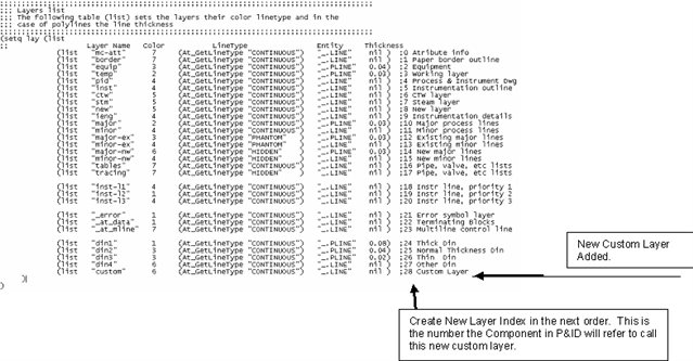
4. Search for "Layers list". The Layers list section will appear. This is how AutoPLANT defines all layers used.
5. Copy an existing line and modify it to create a new layer call. Add new layer created as shown below:
6. Save and Exit the PID-SUP.LSP file.
7. Open AutoPLANT P&ID.
8. Turn on Symbol Manager if it doesn't appear already. (P&ID > Symbol Manager).
9. Find the component in the list. If it doesn't exist add it.
10. Right Click and select "Edit Menu Item..."
11. Modify the Layer Index as shown below:
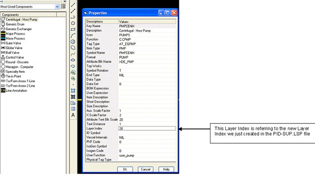
12. Place new component by drag and drop via the Symbol Manager system or via the Menu System. The new component should be placed on the newly created layer by default.
See Also
External Links
Bentley Technical Support KnowledgeBase
Comments or Corrections?
Bentley's Technical Support Group requests that you please confine any comments you have on this Wiki entry to this "Comments or Corrections?" section. THANK YOU!