| Product(s): | RAM Frame, Ram Concrete | ||
| Version(s): | 13.00.00.00 or later | ||
| Environment: | N/A | ||
| Area: | Modeling |
Meshing and Segmentation in RAM Frame or Concrete
General
Lateral walls, 2-way decks and semi-rigid diaphragms are all composed of shell elements in Ram Frame Analysis and Ram Concrete. The subdivision of these elements into smaller pieces is commonly referred to as meshing. In Ram Frame, the size of the mesh is controlled by the “Maximum distance between nodes” parameter in Ram Frame – Criteria – General (also under Criteria - Diaphragm).
Furthermore, when a lateral beam has an internal node at a column or brace end, the member is segmented in the finite element model and represented by two segments. These finite element segments are denoted by the use of i’ and j’ in the member force results. The first segment ends are i and j’ and the second segment ends are i’ and j. Therefore, i’ and j’ are always the ends at the internal node.
Common Meshing and Segmentation Issues
When two-way deck, semirigid diaphragms or lateral walls are present in the model, Ram Frame will go through a meshing process when you start the analysis. You can also start the meshing process by using the View - Meshed floors, View - Meshed walls or Generate Analytical Model tools.
Occasionally, errors or warnings occur during this process. Some examples are below:
Triangular or Very Distorted Quad Shell Elements Found
This particular warning became more pronounced in version 15.04 as presented in the warning above. Prior versions listed such warnings in the meshing log only. A distorted mesh does not generally cause the program to malfunction, but the mesh of the deck (and walls) should be reviewed in these cases. Adjustments in the mesh size or other parameters set under Criteria - Diaphragm can sometimes resolve it.
Deck Layout
Typically, these errors are related to the deck polygons (or occasionally the surface loads). Excessive overlapping polygons and subtle overlaps between polygons can cause problems for the program algorithms. Also, deck polygons that do not align with beam and wall center lines or do not extend to the slab edge will cause problems.
To diagnose these types of issues, in a copy of the model apply a deck to the entire floor. That will delete the existing polygons and should resolve the meshing issue. Then, carefully go back and remodel the partial polygons. Enter Ram Frame and generate the analytical model after each modification to make sure the problem has not returned.
Sloped Framing
When modeling decks on sloped framing, a separate deck polygon is required for each plane or surface of the framing. It is imperative that sloped two-way or semi-rigid diaphragms lie in the plane of the supporting framing. The plane of the diaphragm is defined by three points which are selected based on the way the deck polygon was modeled. If you have sloping framing, the column offsets must be very precise. Where there are multiple planes, there must be a separate deck polygon that corresponds to each plane. If the deck polygons on sloped framing don't match the slopes in the framing there will also be a rift in the 3D view as described here.
Any deviation in the plane of the deck and the plane of the framing can also lead to multiple close nodes or meshing problems when the deck is semi-rigid or two-way.
Invalid Element Orientation.
In some cases the semi-rigid diaphragm will mesh successfully but, on close examination, the nodes of the diaphragm will deviate vertically from the nodes of the frames or walls which will lead to a model instability.
Perimeter Beams (framing) vs. Slab Edges for Diaphragm Exterior Boundary
When a structure has a complete perimeter of beams or walls the user can simplify the meshing of the diaphragm by terminating at the perimeter beam center line. This is controlled by the Criteria - Diaphragms - Diaphragm Boundary setting by using the second option. "Use Beams for Exterior Boundary". This is recommended for semi-rigid diaphragms with small slab edge overhangs in particular.
On the other hand, if the model is a free form, 2-way deck without a continuous perimeter then it's important to only use the first option, "Use Slab Edges for Exterior Boundary".
We have seen cases where a large slab might be clipped back to an interior elevator core only when the beams options is used. This generates a warning in the meshing dialog but that can be overlooked.
Example of a diaphragm that is properly meshed to the exterior slab edges
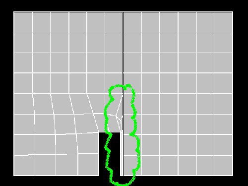
Example of a diaphragm that is excessively clipped to a small set of walls that define a "perimeter"
Regardless, always use the control View - Meshed Floors to visually inspect the resulting floor mesh before running the analysis.
Brace Incidence, Column Alignment, & "Less than 2 nodes" error
Other meshing and segmentation issues stem from subtle discrepancies in linear member end coordinates. This can even affect models that include only beams, columns and braces.
Common error messages during the analysis as “invalid distance between nodes”, or "Less than 2 nodes found for beam..."
For the latter error the program will indicate the beam and level where the problem is located.
When member intersections are modeled accurately, there is a single node at the intersection of the members. If there is a slight misalignment, there will be two nodes that are close together, and if those points are "too close" together the "less then 2 nodes" error will occur.
These misalignments are most common in imported models and usually where the end of a brace misses the beam/column joint or where the columns do not align between stories. A good way to identify if there are close nodes is to view the node numbers graphically in plan and elevation. If you have two numbers that appear to be on top of each other as shown below, then you know there are two nodes very close to one another. These issue cannot typically be resolved with changes in the mesh criteria since the beams and braces themselves are the source of the problem. The merge node tolerance should never be set larger than an inch.
To resolve the issue, go to Ram Modeler and review the member end coordinates using the Layout – Show, or the Integrity - Align commands. Them move, align or replace the offending members being careful to snap to key points like grids.

Another symptom can be junk results for member forces (with alphanumeric values like -#1.J) which will cause a crash in the steel post processing modes.
Wall Openings
A similar issue can occur with wall openings. If there is a thin sliver of wall between the edge of an opening and the edge of a wall, this will produce a poor mesh. Look for poor wall meshes by using Ram Frame – View – Meshed Walls. Modify the size of the opening in elevation mode in Ram Modeler so the opening aligns with the wall edge.
Other Recommendations
Generally, the finer the mesh is, the more accurate the deformations are. However, using a very fine mesh increases analysis time. To determine an adequate mesh size, systematically decrease the maximum distance between nodes until you see an acceptable level of convergence in the displacements.
When you have one way decking, the slab edge is offset from the perimeter beam/wall loop. If there are lateral beams/walls on the perimeter, there will be a poor mesh in the area between the edge of the slab and the lateral beam/wall if the slab edge offset is small. To avoid this, use the “Use Beams for Exterior Boundary” option in Ram Frame – Criteria – Diaphragm.
Avoid using sloped semirigid diaphragms. If the roof has a subtle slope, conservatively model the roof flat at the highest elevation.
Tips for Correcting Problems
In the Modeler under the integrity menu are two powerful commands, Align Columns and Align walls. These tools allow you to reposition walls or columns on some or all levels so that they align through the height of the structure. The objects can be aligned to one another, or to a grid intersection or any user provided coordinate.
This is similar to moving grids. When the supports are moved all of the supported framing is also adjusted or stretched. Since this can have unexpected effects, it's always best to back up the file before using these adjustments.
Another tip is to use the Layout - Slab - Deck Assign - Change Polygon option so that you can stretch the corners of the deck polygons. The edge of deck polygons should typically align with beams or walls. Deck changes should not occur mid-bay except when using 2-way decks. At the edges of the structure it is fine for the decks to extend you to the slab edge vertices or even beyond, but in cases where the slope is complicated, it may be simpler to stop the deck at the perimeter framing. In these cases the program will assume a like type deck on the overhanging portion of the slab edge.
See Also
[[Ram Modeler Grid Import Tool]]
[[RAMSS Two Way Decks]]